Homogenization theory for designing graded viscoelastic sonic crystals*
[Qu Zhao-Liang, Ren Chun-Yu, Pei Yong-Mao† , Fang Dai-Ning‡]
, Fang Dai-Ning‡]
|
|


Corresponding author. E-mail: peiym@pku.edu.cn
Corresponding author. E-mail: fangdn@pku.edu.cn
Project supported by the National Basic Research Program of China (Grant No. 2011CB610301).
In this paper, we propose a homogenization theory for designing graded viscoelastic sonic crystals (VSCs) which consist of periodic arrays of elastic scatterers embedded in a viscoelastic host material. We extend an elastic homogenization theory to VSC by using the elastic-viscoelastic correspondence principle and propose an analytical effective loss factor of VSC. The results of VSC and the equivalent structure calculated by using the finite element method are in good agreement. According to the relation of the effective loss factor to the filling fraction, a graded VSC plate is easily and quickly designed. Then, the graded VSC may have potential applications in the vibration absorption and noise reduction fields.
In previous years, interest in sonic crystals due to their attractive physics and potential applications has been aroused. Sonic crystals can exhibit acoustic bandgaps where acoustic waves are forbidden and control the propagation of the acoustic waves.[1– 4] Many acoustic devices have been designed and they demonstrate an extensive application prospect, such as filters, sound barriers, waveguides, etc.[5– 11] But realistic structures are dissipative and have losses. Transmission of two-dimensional (2D) VSC has been investigated theoretically and experimentally.[12– 14] The bandgaps of one-dimensional (1D) and 2D VSC have been demonstrated by using the plane wave expansion method.[15, 16] In addition, graded sonic crystals can be used to guide acoustic waves without the bandgap effects or defects.[17] The graded physics can be realized by gradual modifications of the lattice constant, the filling fraction, or the material parameters.[18] The graded concept has been introduced to design acoustic devices, such as acoustic beamwidth compressors, gradient negative refractive index lens, acoustic bending waveguides, etc.[17, 19– 22] However, most research on graded sonic crystals has been limited to elastic materials, and the viscoelastic properties are less considered.
Homogenization theory provides an effective method to deal with inhomogeneous problems. In the regime of a large wavelength, a sonic crystal behaves as an effective homogeneous acoustic material, and effective parameters of elastic sonic crystal have been calculated, such as effective sound speed, effective density, effective elastic constant, and effective refractive index.[23– 27] However, to date there has not been an effective homogenization theory to guide the design of the graded VSC.
In the present work, we propose a homogenization theory for designing 2D VSC in a large wavelength regime and derive an exact analytical formula for effective loss factor. According to the elastic-viscoelastic correspondence principle, the homogenization theory of elastic sonic crystals is developed for VSC. Then, we compare the simulation results of VSC and the equivalent structure by using the finite element method (FEM) and find that they match well. Finally, according to the relation of the effective loss factor to the filling fraction, we quickly design a graded VSC plate.
Consider a 2D VSC with square lattices, and the elastic cylindrical scatterers are embedded periodically in a viscoelastic matrix material.
The motion equation in an inhomogeneous isotropic elastic solid can be expressed as

where ∇ is the Hamilton operator, λ and μ are the elastic constants of material, u is the displacement vector, r is the radius vector, t is the time, and ρ is the mass density.
For the elastic periodic structure, in the time domain the Bloch– Floquet wave can be expressed as

where k is the wave vector, ω is the angular frequency, i is the imaginary unit, and the subscript e denotes the elastic wave.
Inserting Eq. (2) into Eq. (1) leads to

The geometric equation can be expressed as

where ε ij(t) is the strain tensor, ui (t) and uj (t) are the displacement components, and xi and xj are the coordinate components (i, j = 1, 2, 3).
The Bloch boundary condition can be expressed as

where a is the lattice constant.
When the simple harmonic waves propagate in the viscoelastic structure, in the frequency domain the displacement can be expressed as

where the subscript v denotes the viscoelastic wave.
Inserting Eq. (6) into Eq. (1) leads to

After Fourier transformation, the geometric equation can be expressed as
And the Bloch boundary condition can be expressed as

It should be noted that the forms of motion equation, geometric equation, and Bloch boundary condition in the time and frequency domain are the same.
Then, the elastic-viscoelastic correspondence principle is available, and the solution of elastic problem in the time domain can be treated as the solution of corresponding viscoelastic problem in the frequency domain.
In the low frequency domain, the dispersion relation of sonic crystal is linear, and one wavelength covers many lattice periods. A sonic crystal behaves like a homogeneous medium whose effective parameters are related to the filling fraction. According to Ref. [26], the effective Young’ s modulus is expressed as

where f is the filling fraction, E1 and E2 are the Young’ s moduli of embedded and host materials, respectively.
The effective mass density is expressed as

where ρ 1 and ρ 2 are mass densities of embedded and host materials, respectively, and we assume that they are independent of time.
In the frequency domain, the frequency-dependent Young’ s modulus of viscoelastic host material can be expressed as

where E2R (ω ) is the real part of the complex Young’ s modulus, and E2I (ω ) is the imaginary part.
Inserting Eq. (12) into Eq. (10) leads to
where E1 is the Young’ s modulus of the elastic embedded material and 
Finally, we define the analytical effective loss factor as
Under the large wavelength approximation, this loss factor is dependent on filling fraction, angular frequency, and Young’ s moduli, and describes the dissipation property of the VSC in which the simple harmonic acoustic wave propagates.
Here, the VSC is composed of a single row of the unit cells constituting a cylinder with radius r arranged in a square lattice with lattice parameter a = 0.02 m. We assume that the unit cell can be replaced by a homogenous square unit cell with side length a [see the inset in Fig. 1]. The filling fraction f is expressed as

In the time domain, the viscoelastic material is characteristic of the time-dependance of elastic constants. For the standard solid model of viscoelastic material, the Young’ s modulus can be expressed as

where E0 and E∞ are the initial and final state value of the complex modulus and τ E is the relaxation time. The parameters of the materials are listed in Table 1. In the case of harmonic motion, the time-dependance of elastic constant can be replaced by the frequency-dependance, namely,
where F(· ) denotes the Fourier transformation.
| Table 1. Parameters of the materials studied in this work. |
When the simple harmonic plane wave is incident on one side of the structure, the reflection coefficient can be expressed as

The impedance of the water Z0 can be expressed as

where ρ 0= 1000 kg/m3 is the water density and c0= 1300 m/s is the water velocity.
The impedance of the input surface of the structure can be expressed as

where p1 is the nodal pressure of the input surface, and vn1 is the nodal normal velocity of the input surface.
The transmission coefficient can be expressed as

Here, the impedance of the output surface of the structure can be expressed as

where p2 is the nodal pressure of the output surface, and vn2 is the nodal normal velocity of the output surface.
Then, the absorption coefficient can be expressed as

where | R| is the modulus of R, and | T| is the modulus of T.
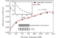
For a given filling fraction, it is easy to obtain the relationship between the effective loss factor and the angular frequency [see the inset in Fig. 1], according to Eqs. (14) and (17). It is found that the effective loss factor decreases with the increase of the angular frequency. The relationship between the operation angular frequency and the absorption coefficient can be obtained by giving the loss factor using FEM analysis. From Fig. 1, it is observed that with the increase of the angular frequency, the wavelengths decrease and the enhanced scatter effect results in the increasing of the absorption coefficients for both the structures. Moreover, the difference in absorption coefficient between both structures is found to become more visible in the larger frequency domain.
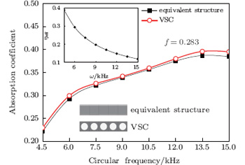 | Fig. 1. Plots of absorption coefficient versus operation angular frequency. The inset shows the relationship between effective loss factor and angular frequency. The solid squares denote the equivalent structure, and the empty circles represent the VSC. |
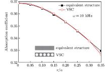
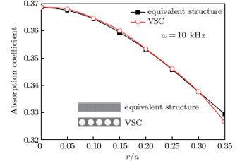 | Fig. 2. Plots of absorption coefficient versus filling fraction. The solid squares denote the equivalent structure, and the empty circles represent the VSC. |
For a given angular frequency, the relationship between the effective loss factor and the filling fraction (r/a) can be obtained (Fig. 3) according to Eqs. (14) and (17). It is found that the larger the filling fraction, the smaller the effective loss factor is. From Fig. 2, it is found that the two results coincide well with each other. Besides, a larger fraction of elastic material can reduce the fraction of the viscoelastic material, which plays a leading role in the sound absorption property. Consequently, the absorption coefficients of both structures decrease with the increase of the filling fraction. From Figs. 1 and 2, the significant influence of the angular frequency on the absorption property is found to be larger than that of the filling fraction.
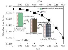
The loss factors of a graded index medium can be discretized, and the discrete loss factors are approximated by using the VSC at a specific angular frequency. Suppose that we are going to design a 2D sound absorption plate and sound in the absorption structure can propagate with some dissipations. First, we give the loss factor distribution (Fig. 3) of the graded index medium plate [see the inset (a) in Fig. 3] along the sound propagation direction (x). Then, we obtain an equivalent plate [see the inset (b) in Fig. 3] by discretizing the successive graded index medium plate. The equivalent plate is composed of several rectangular parts with size length a = 0.02 m along the sound propagation direction (x). Finally, according to Eq. (14), a graded VSC plate [see the inset (c) in Fig. 3] with spatially varying radius of elastic cylinder is designed to replace the equivalent plate. The graded VSC plate can also realize a graded index medium.
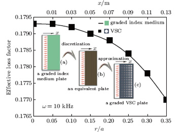 | Fig. 3. Design of a graded VCS plate. Inset (a) shows the graded index medium plate, inset (b) shows an equivalent plate, and inset (c) shows a graded VSC plate. The graded VSC plate is composed of many rows of unit cells, and the filling fraction (r/a) of the unit cell in a single row becomes larger along the wave propagation direction (x). The solid line represents the graded index medium, and the solid squares denote the VSC. |
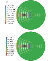
From Figs. 4(a) and 4(b), we can see that the amplitude of pressure distribution of graded VCS plate is similar to that of the discrete equivalent plate. When the acoustic waves are incident on both structures, the reflection plays a leading role and few acoustic waves can travel through the structures. This may result from the impendence mismatch. Besides, some acoustic waves travel around the structures near the edge due to the size effect.
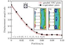
From Fig. 5, we can see that the displacement amplitude of the nodes along the wave propagation direction (x) decreases as the travel distance increases. This demonstrates that both of the structures can exhibit a sound absorption property. The attenuation law approximately corresponds to the exponential function. At the same time, we give the displacement distributions of both of the structures [see insets (a) and (b) in Fig. 5]. In the interiors of both of the structures, there are some local resonance regions. This may account for the absorption property of the structure.
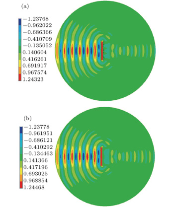 | Fig. 4. External pressure field distributions for (a) the graded VSC plate and (b) the discrete equivalent plate. |
 | Fig. 5. Displacement amplitudes of the nodes along the wave propagation direction (x). Inset (a) shows the displacement distributions of the graded VSC plate, and inset (b) shows the displacement distributions of an equivalent plate. The graded VSC plate is composed of many rows of the unit cells, and the filling fraction (r/a) of the unit cell in a single row becomes larger along the wave propagation direction (x). The solid squares denote the equivalent structure, and the empty circles represent the graded VSC plate. |
In this paper, we extend the homogenization theory of elastic sonic crystals to VSC based on the elastic-viscoelastic correspondence principle. We obtain the effective parameters of VSC and propose the concept of the effective loss factor. The FEM simulation results of VSC coincide well with those of equivalent structures. Finally, according to the relation of the effective loss factor to the filling fraction, we quickly and easily design a graded VSC plate that can replace the graded index medium plate whose loss factors are regularly distributed along the sound propagation direction (x). The graded VSC may have potential applications in the vibration absorption and noise reduction fields.
| 1 |
|
| 2 |
|
| 3 |
|
| 4 |
|
| 5 |
|
| 6 |
|
| 7 |
|
| 8 |
|
| 9 |
|
| 10 |
|
| 11 |
|
| 12 |
|
| 13 |
|
| 14 |
|
| 15 |
|
| 16 |
|
| 17 |
|
| 18 |
|
| 19 |
|
| 20 |
|
| 21 |
|
| 22 |
|
| 23 |
|
| 24 |
|
| 25 |
|
| 26 |
|
| 27 |
|