

Controlling an acoustic wave with a cylindrically-symmetric gradient-index system*
[Zhang Zhea), b) , Li Rui-Qia) , Liang Bina), c) , Zou Xin-Yea) , Cheng Jian-Chuna), b)†  ]
]
]
|
|


Corresponding author. E-mail: jccheng@nju.edu.cn
Project supported by the National Basic Research Program of China (Grant Nos. 2010CB327803 and 2012CB921504), the National Natural Science Foundation of China (Grant Nos. 11174138, 11174139, 11222442, 81127901, and 11274168), NCET-12-0254, and the Project Funded by the Priority Academic Program Development of Jiangsu Higher Education Institutions, China.
We present a detailed theoretical description of wave propagation in an acoustic gradient-index system with cylindrical symmetry and demonstrate its potential to numerically control acoustic waves in different ways. The trajectory of an acoustic wave within the system is derived by employing the theory of geometric acoustics, and the validity of the theoretical descriptions is verified numerically by using the finite element method simulation. The results show that by tailoring the distribution function of the refractive index, the proposed system can yield a tunable manipulation of acoustic waves, such as acoustic bending, trapping, and absorbing.
In recent years, considerable efforts have been devoted to the development of optical metamaterials and artificial structures with optical gradient index (GRIN) medium in which the refractive index varies from point to point.[1– 6] These intense investigations have created new concepts and widened the scope of application, such as cloaks, [7– 19] concentrator, [11, 20] wave rotator, [21] and imaging devices.[22, 23] A rigorous full wave analysis in the GRIN photonic system has already been presented.[24] The propagation of acoustic wave (another classical wave) in an acoustic GRIN system will be affected in a similar manner. It has been extensively proven that acoustic GRIN medium can be realized by properly selecting the structural parameters of sonic crystal (SC)[25– 34] in the direction transverse to the acoustic propagation or by employing acoustic metamaterials formed by coiling up space.[35] It is therefore expected that acoustic GRIN systems may also have the potential to manipulate acoustic waves in a variety of ways, which would have deep implications for acoustic devices, acoustic applications, and the field of acoustics in general. Although the acoustic GRIN media have been extensively investigated in the literature, [25, 28– 37] the primary attention has only focused on the ability to design acoustic lenses. Li et al. have investigated the possibility of using a cylindrically-symmetric GRIN shell to guide the incident acoustic wave into the center spirally, which may be regarded as an acoustic omnidirectional absorber (AOA) and may has a prospect for applications such as noise control and underwater acoustically anechoic techniques.[38] In the above studies, however, only a highly-limited case is considered where the refractive index distribution along the radial directional exactly follows an inverse-square law. The potential of acoustic GRIN system to yield various kinds of acoustic manipulations has not been fully explored yet. Moreover, a detailed theoretical description of the wave propagation in acoustic GRIN system is still lacking despite its significance for comprehending the underlying physics in such a kind of system.
In the present paper, we consider an acoustic gradient-index system with cylindrical symmetry and numerically investigate the wave propagation in such a system. Geometric acoustic theory is employed to predict the acoustic trajectory in the system. We then perform finite-element-method-based simulations to numerically verify the validity of the geometric acoustic theory. The numerical results are proven to agree well with the geometric results. The numerical results demonstrate the potential for the proposed system to yield various kinds of manipulations on acoustic waves, such as acoustic bending, trapping, and absorbing, which can be tuned by tailoring the distribution function of refractive index. The proposed system comprises a cylindrically-symmetric positive-index medium only, and thus has an omnidirectional and broadband functionality. With the flexibility of controlling acoustic waves in different ways. Moreover, such a system may find applications in various cases where special manipulations of acoustic waves are required.
Here we give mathematical formulations for the system (see Fig. 1(a)), which consists of a cylindrically symmetric cylinder with the radius-dependent sound velocity c(r) given as follows:
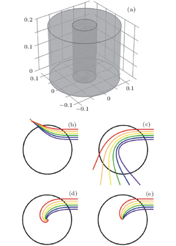 | Fig. 1. (a) Schematic illustration of the proposed model; ((b), (c), (d), and (e)) the ray trajectories predicted from Eq. (2) for four particular cases, i.e., α is equal to − 1, 1, 2, and 3 respectively, where the core radius rc is much smaller than the shell radius R. |
where c0 refers to the sound velocity of the background medium, R denotes the radius of the system, and α ≠ 0 is an adjustable parameter, which is a constant. In the middle of the cylinder there is an absorber whose radius rc is much smaller than the radius R of the shell. The acoustic refractive index n(r) can then be written as

From Eq. (2) it is expected that the closer to the center of the system the acoustic wave is, the higher the acoustic refractive index will become. Note also that when propagating within an inhomogeneous medium, the acoustic wave will always bend towards the medium with a larger refractive index. Hence, we can control the direction of the acoustic wave propagation by manipulating the acoustic refractive index.
For easier derivation and to better understand how the proposed model guides an acoustic wave, we first derive the acoustic ray trajectory by employing the theory of geometric acoustics. In a three-dimensional (3D) spherical symmetric medium, the ray trajectory in the shell is a plane curve and the plane in which the trajectory is located passes through the origin. Hence, the trajectory equation is employed in two-dimensional (2D) cylindrically-symmetric coordinates only and can be derived as

where (r, θ ) are polar coordinates and q = R sin ϕ denotes the distance between the incident ray (before entering the system) and the center of the system.[24] Eqs. (2) and (3) yield the ray trajectories inside the system shell in polar coordinates as
The choice of the particular parameter α , which will be discussed carefully later, leads to different cases. For an incident acoustic wave coming from outside, it is expectable that the acoustic ray trajectory is dependent on the refractive index distribution of the model, which is exclusively determined by the selection of α . Figures 1(b)– 1(e) illustrate the typical results when four particular values of α are chosen to be − 1, 1, 2, and 3, respectively. It is proven that the value of α significantly affects the path along which an acoustic wave propagates within the model. From Figures 1(b) and 1(c) one can clearly observe that in the cases of α < 2, any ray with non-zero value of q is bent before reaching the center region. The minimal distance between the trajectory and the center can be analytically predicted to be dmin = R(sin φ )2/(2 − α ). The difference between the cases where the signs of α are different lies in the direction of the bending effect: the incident beam is bent inward with respect to the center for α < 0 and outward for α ≥ 0. For the case where α ≥ 2, on the other hand, the incident ray is distorted and winds spirally towards the center of the system, which are shown in Figs. 1(d) and 1(e). Moreover, the extent to which the trajectory is bent increases as we manually increase the value of α or reduce the value of q.
The results shown in Fig. 1 suggest the possibility of tailoring the refractive index distribution in the proposed model to yield different kinds of manipulations on incident waves, which can be achieved easily by adjusting the value of α . This will be further explored and verified later via numerical simulation.
To further verify our geometric acoustic theory results, numerical simulations based on the finite element method are performed to study the performance of the proposed system. In the numerical simulation, the outer boundary is set to be R = 6 cm. For simplicity and without loss of generality, the central cavity is assumed to be an ideal absorber and the boundary of the absorber core is set to be rc = 2 cm. Water (ρ 0 = 998 kg/m3, c0 = 1483 m/s) is chosen as the background medium. A Gaussian beam with frequency f1 = 1 × 10⁵ Hz and a plane wave with frequency f2 = 2 × 10⁵ Hz are chosen as the incident waves.
In the center of the system there appears a physical singularity, owing to the inherent singularity to the GRIN medium. To avoid this singularity, an impedance-matched absorption core is employed in the center of the system. So, no matter whether the incident sound waves are deflected inward or outward, they do not go through the singularity center. In this way it is assured that all of the scattering wave phenomena are properly ascribed to the GRIN medium.
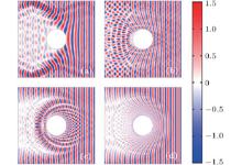
Figures 2 and 3 display the results for the cases where the incident waves are assumed to be a Gaussian beam and a plane wave, respectively. From Fig. 2(a), which illustrates results for the typical case of α = − 1, it is apparent that the incident Gaussian beam undergoes a beam bending effect and the bent acoustic trajectory is in good agreement with the ray-acoustic prediction, which is given by Eq. (4). When being incident, the beam spirals outward away from the central region and it then escapes out of the system. Thus, the system plays a role in rejecting and bending sound waves. The angle of bending depends on the decisive parameter α , and the distance q between the incident beam and the center of the system. As a result, when the incident wave is a plane-acoustic wave, a shadow region is formed behind the absorptive core, whose cross section is much larger than that of the core. This beam-splitting-like property leads to a strong shielding effect preventing the incident wave from reaching the enlarged shadow region. For the case of 0 < α < 2, as illustrated in Fig. 2(b) where α is chosen as a particular value of α = 1, the dependence of the trajectory of incident Gaussian beam is quantitatively similar to that in the previous case, except that the bending direction of the beam is reversed, i.e., the beam is bent inward rather than outward from the center. For a plane-wave incident, it is apparent that there is an interference pattern behind the absorptive core where the acoustic trajectories intersect and the wave interactions necessarily occur. The bending effects of the cases α < 0 and 0 < α < 2 can be tailored conveniently and effectively by adjusting the values of only two parameters α and q, which can be applied to acoustic control, which may enable the design of novel acoustic devices, such as beam splitter, sound shield, and insulator, with potential applications in various situations.
 | Fig. 2. Simulated pressure field maps for the incident wave in which a Gaussian beam with frequency f1 = 1 × 10⁵ Hz is considered, with α being − 1 (a), 1 (b), 2 (c), and 3 (d). |
 | Fig. 3. Simulated pressure field maps for the incident wave in which a plane wave with frequency f2 = 1 × 10⁵ Hz is considered, with α being − 1 (a), 1 (b), 2 (c), and 3 (d). |
As α increases to two, the winding field pattern of the sound wave undergoes a change. The incident Gaussian beam exhibits a spiral trajectory toward the core and can never escape out of the system. Finally, the beam is trapped in the system and the energy entering into the system is absorbed by the absorption core. Besides, as α increases further, the beam becomes less spiral. It is demonstrated that while α is equal to 3, the beam spirals into the center with shorter path than α equal to two. It can also be seen that there are more beams of the case α = 3 spiraling into the center than those of the case α = 2, leading to a better absorption effect. For the plane wave incidence, the system expands the absorption region, and leaves a huge blank area behind. There is no significant difference except the absorption efficiency between cases of α = 2 and α = 3. In terms of the practical realization, higher orders of α represent increasingly difficult fabrication problems due to their correspondingly larger values of the local sound velocity and its gradients. Therefore, most studies and experiments focus on the case of α = 2.[38– 42]
In addition, it is worth mentioning that the structure of the system is composed of positive-index axial-symmetry materials, which facilitates its realization and application. Furthermore, the effect we describe is essentially non-resonant, leading to a nearly perfect absorption for arbitrary wavelength, as long as the size of the system is substantially larger than the wavelength of the incident wave. In practice, the seemingly ideal assumption of continuous refractive-index distribution can be conveniently implemented by employing homogeneous concentric layers of sonic crystal.[42] The designed system has cylindrical symmetry and consists of two parts, a shell that bends the sound towards the center and a core that dissipates its energy. The shell is made of a metamaterial that perfectly matches the acoustic impedance of air and behaves like a gradient index lens. The required refractive index distribution in the system can then be approximately implemented by properly tuning the volume concentrations of the two materials in the sonic crystal.
In this paper, wave propagation in an acoustic gradient-index system with cylindrical symmetry is described and demonstrated numerically to yield various kinds of manipulations on acoustic waves. On the basis of geometric acoustics theory, we derive the acoustic trajectory for predicting the behavior of an incident wave inside this structure. The results show that by tailoring the distribution function of refractive index, the proposed system can yield different kinds of manipulations on acoustic waves, such as acoustic bending, concentrating, and absorbing. Our results may open up new possibilities for designing acoustic device in various acoustic applications.
| 1 |
|
| 2 |
|
| 3 |
|
| 4 |
|
| 5 |
|
| 6 |
|
| 7 |
|
| 8 |
|
| 9 |
|
| 10 |
|
| 11 |
|
| 12 |
|
| 13 |
|
| 14 |
|
| 15 |
|
| 16 |
|
| 17 |
|
| 18 |
|
| 19 |
|
| 20 |
|
| 21 |
|
| 22 |
|
| 23 |
|
| 24 |
|
| 25 |
|
| 26 |
|
| 27 |
|
| 28 |
|
| 29 |
|
| 30 |
|
| 31 |
|
| 32 |
|
| 33 |
|
| 34 |
|
| 35 |
|
| 36 |
|
| 37 |
|
| 38 |
|
| 39 |
|
| 40 |
|
| 41 |
|
| 42 |
|