

A 23.75-GHz frequency comb with two low-finesse filtering cavities in series for high resolution spectroscopy*
[Hou Leia) , Han Hai-Niana)†  , Wang Wei
b) , Zhang Longa) , Pang Li-Huia) , Li De-Huaa) , Wei Zhi-Yia)‡ ]
, Wang Wei]
|
|


Corresponding author. E-mail: hnhan@iphy.ac.cn
Corresponding author. E-mail: zywei@iphy.ac.cn
Project supported by the National Basic Research Program of China (Grant No. 2012CB821304) and the National Natural Science Foundation of China (Grant Nos. 11078022 and 61378040).
A laser frequency comb with several tens GHz level is demonstrated, based on a Yb-doped femtosecond fiber laser and two low-finesse Fabry–Pérot cavities (FPCs) in series. The original 250-MHz mode-line-spacing of the source comb is filtered to 4.75 GHz and 23.75 GHz, respectively. According to the multi-beam interferences theory of FPC, the side-mode suppression rate of FPC schemes is in good agreement with our own theoretical results from 27 dB of a single FPC to 43 dB of paired FPCs. To maintain long-term stable operation and determine the absolute frequency mode number in the 23.75-GHz comb, the Pound–Drever–Hall (PDH) locking technology is utilized. Such stable tens GHz frequency combs have important applications in calibrating astronomical spectrographs with high resolution.
Laser frequency combs with multi-gigahertz spacing (high repetition rate) have emerged as promising tools of metrology for a variety of applications, [1, 2] opening a new field in the development of high precision astronomical spectroscopy (HPAS).[3– 6] Multi-gigahertz spacing frequency combs used to calibrate an astronomical spectrograph would support high precision radial velocity measurement up to 1 cm/s, [7] enabling many important astronomical research projects, such as searching for terrestrial-mass planets in earthlike orbits, measurement of the cosmic expansion velocity, and observation of temporal variation in fundamental constants. The key of HPAS is that the individual mode lines of a comb must be distinguished by existing dominant astronomical spectrographs. For example, a resolution of 5 × 10⁴ at 1030 nm would require a comb with mode spacing of at least 6 GHz to ensure that the modes are separated by at least three resolution elements. A promising path to produce large spacing lines is to spectrally filter intermediate comb modes with a Fabry– Perot cavity (FPC).[8] Based on existing laser combs (source-comb) with mode spacing in the range of hundreds MHz and 1 GHz, such as Ti:sapphire laser combs, Yb:fiber laser combs, and Er:fiber laser combs, several kinds of multi-gigahertz combs, also called astro-combs, have been developed. In 2008, Chih– Hao Li et al. were first to report a 40-GHz line spacing astro-comb based on an octave-spanning Kerr lens mode-locked Ti:sapphire laser with 1-GHz repetition rate.[7] Next, a 12.5-GHz-spaced comb and an 18-GHz comb were obtained in succession using an erbium-doped fiber laser[9] and a Yb-doped fiber laser, both with the same repetition rate of 250 MHz.[10]
In calibrating high resolution astronomical spectrographs, side-mode suppression of the mode-filtering system is essential for improving the accuracy of the calibration. Since individual lines are eventually deconvoluted with the known point spread function of the spectrograph for the ultimate resolution, insufficient suppression of side modes that lie within the resolution of the spectrograph will result in systematic shifts of the calibration curve. To get a high suppression of neighboring modes, a high finesse FPC is required. However, using a singly filtered FPC with high finesse not only induces extra difficulty in alignment but it also, and more seriously, generates small irregularities of the filter mode spacing that can prevent the setup from being effective over a wide optical bandwidth. Therefore, two or three low finesse Fabry– Perot filter cavities in series[11– 14] are proposed to solve this problem. In addition, in the astro-comb, the frequency stabilization of the comb mode should be traced to the standard microwave clock source so that it can maintain stability and reproducibility over a long period to support the detection of distant planets and the universe’ s velocity of expansion.
For this paper, we first simulated the side-mode suppression rate of different mode-filter FPCs schemes, according to the multi-beam interferences theory. With the guidance of this simulation, we chose the optimum filter FPC scheme to improve the accuracy of astronomical wavelength calibration. In the experiment, based on a 250-MHz repetition rate passively mode-locked Yb:fiber comb, we realized an astro-comb with mode-line spacing exceeding 20 GHz and side-mode suppression up to 43 dB by use of two external low-finesse FPCs in series, nearly reaching the theoretical limit of this kind of scheme. The modes of an astro-comb are absolutely determined by a continuous wave (CW) laser. The CW laser ensures the same mode passing through the FPCs while connecting and stabilizing the FPCs to the comb source over a long time period.
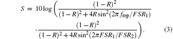
As described above, although a single high finesse FPC has the ability to broaden the line spacing of a comb with high side-mode suppression, this approach has always been accompanied by the problems of finite spectral bandwidth and difficulties in stabilizing the length of the FPC, degrading the accuracy of the astronomical wavelength calibration. In order to keep high side-mode suppression rate and wide bandwidth at the same time, the scheme of several low finesse FPCs combination has been utilized in some astro-combs. In our experiment, to design for conversion from 250 MHz to a frequency comb of more than 20 GHz with a side-mode suppression rate of up to 40 dB, we first performed a theoretical study of side-mode suppression for single and double cavities. In order to compare six filtering schemes, we assumed that all of the FPCs are composed of mirrors with 99.4% reflectivity; the source-comb has line spacing of 250 MHz (frep) and the repetition-rate of the astro-comb is Mfrep, where M = m1m2 with m1 being the filter number of the first cavity and m2 being the filter number of the second cavity. Choose the FSR (free spectral range) of each FPCs as follows: (i) FSR = Mfrep for a single FPC; (ii) FSR1 = FSR2 = Mfrep for two identical FPCs in series; (iii) FSR1 = m1frep and FSR2 = m1m2frep for two different lengths of FPCs in series. For a single filter cavity forming mirrors of reflectivity R, the spectral transmission function [15] is given by

with f being optical frequency and FSR being free spectral range.
Therefore, the side-mode suppression rate of FPC can be written by

In a similar way, the side-mode suppression rate of double-FPC can be written by
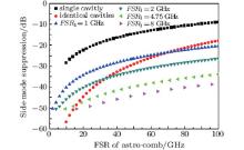
Under similar considerations, we can get the suppression effect of more FPCs in series. Figure 1 shows the side-mode suppression for single and double cavities as functions of filter ratio M. The horizontal axis stands for the line-spacing of the final astro-comb, in the range of 100 GHz from the left to the right, while the vertical axis represents the value of side-mode suppression. From Fig. 1, it could be found that it is possible to choose a suitable filter cavity scheme to achieve a side-mode suppression rate of > 40 dB with the final repetition rate of the final astro-comb exceeding 20 GHz. Although these filtering schemes achieve an astro-comb of more than 20 GHz line spacing, they differ in terms of side-mode suppression. In contrast with a single FPC, a filter system of two FPCs exhibits higher suppression for side modes. Moreover, in the case of double cavities schemes, suppression results largely depend on the FSR of the first filter cavity with the wider FSR. When considering an astro-comb exceeding 20-GHz with > 40-dB side-mode suppression rate and easily boosting the power of pulses in the process of filtering, we must strike a decent balance. Based on the above discussion, we adopt these appropriate parameters for our filter schemes: FSR1 = 4.75 GHz, FSR2 = 23.75 GHz.
 | Fig. 1. The side-mode suppression rate as a function of FSR of astro-comb with different filter systems based on a 250-MHz repetition rate of the Yb:fiber comb. The squares show side-mode suppression with a single FPC. The circles show results of two identical FPCs. The triangles show suppression with a different FSR of the first filter cavity in the series. |
The experimental setup is shown in Fig. 2. The whole 23.75-MHz astro-comb consists of three parts: source-comb, FPCs, and stabilization locking electronics. A passively mode-locked Yb-doped fiber laser, used as the source comb, can directly emit 100 mW, 250 MHz, and 1-ps laser pulses with a center wavelength of 1040 nm. The output of the source comb is divided into three routes for different uses. One route of about 30 mW is selected to construct an f– 2f interferometer for measuring the carrier-envelope offset phase frequency (fceo). Through synchronously locking the fceo and the repetition rate (frep) to the same microwave clock, for example an Rb clock, the optical frequency line of the Yb-doped fiber source laser is absolutely stabilized. A 100-kHz narrow linewidth CW external cavity diode laser at 1030 nm is used to determine the absolute frequency of the astro-comb mode and to make sure that the same mode is passing through FPCs and to stabilize the lengths of the FPCs.
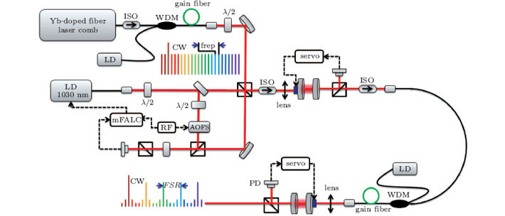 | Fig. 2. Schematic diagram of the astro-comb. The red solid lines represent optical paths, the black solid lines are fiber paths, and the dashed lines show the electrical paths. ISO: optical isolator; WDM: wavelength division multiplexer; LD: laser diode; Gain fiber: Yb-doped fiber; λ /2: half-wave plate; PZT: piezoelectric transducer; PD: photodiode; AOFS: acoustic– optical frequency shifter. |
In order to compensate the power loss induced by filter cavities, two fiber amplifiers are used before the two FPCs to scale the power of the comb. The first amplifier is composed of a pre-amplifier and power amplifier. The pre-amplifier employs 15-cm Yb-doped single-mode gain fiber pumped with one fiber-pigtailed laser diode of 500 mW at 976 nm and the pulses are amplified from 30 mW to 120 mW. The power amplifier is constructed with a 3-m Yb-doped double-clad fiber pumped by an 8-W multimode pump diode at 976 nm. The comb light continues to be amplified to approximately 1.8 W under 6.3-W pump light. With 4.75-GHz FSR of the first filter cavity, a large amount of comb power is reflected from the first FPC and only 20 mW is focused into the second amplifier. The second amplifier has the same parameters as the first, and delivers the light to the second filter cavity with 23.75-GHz FSR.
The 1030-nm CW diode laser is divided into two parts, one part is combined with the comb laser producing the beat frequency detected by an infrared avalanche photodiode (APD) to realize the locking between the CW laser and the original comb through an AOFS, and the other part is mode-matched into the first FPC and the second FPC, using the transmitted signal as the error signal to control the length of the FPCs.
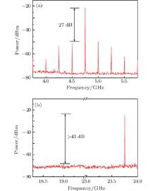
According to the numerical simulation, a multi-low-finesse FPC is suitable for achieving greater suppression of the intermediate modes. We realized an astro-comb with mode-line spacing exceeding 20 GHz in the case of filter ratios of m1 = 19 (FPC length of 31.6 mm) and m2 = 5 (FPC length of 6.3 mm). With a reflectivity of 99.4%, each filter cavity consisted of one flat mirror and one concave mirror with radii of curvature 500 mm and minimal group delay dispersion (< 10 fs2 from 1000 nm to 1100 nm). Under the optimized alignment of the FPCs and the lengths, we adjusted the CW laser and comb beam profiles to match with the TEM00 mode of the FPC at the same time by using two lenses. The length of FPC was scanned periodically or locked by the circuit to drive the PZT. When the FSRs of the FPCs are equal to a multiple integer of the initial repetition rate of the source-comb, a resonance peak appears. When linearly sweeping the length of the filter cavity over more than one FSR with PZT, several peaks of resonance are detected on an oscilloscope. So we need to find the highest peak signal for locking the distance between the mirrors via the PZT pasted on it. In the PDH scheme, the driving current of the CW laser was modulated by, and the transmission signal was used to produce, an error signal in the mixer. As a result, it was possible to keep the pulses in resonance by locking the cavity length. A common means to measure the suppression of side modes is to detect the light after FPC with a microwave spectrum analyzer while the cavity length is locked. Figure 3 exhibits the repetition rate and its high harmonics for the cases of two low-fineness FPCs with FSRs of 4.75 GHz and 23.75 GHz, detected by a high speed photodetector (1437, New Focus Inc.). Figure 3(a) shows that the first filter cavity suppresses the 250-MHz fundamental comb teeth by 27 dB in the RF domain. Figure 3(b) illustrates that the side-modes suppression at 23.75 GHz after the second filter cavity is approximately 43 dB, which is near the theoretical limit of 46 dB. The optical spectra of the pulse after the two external FPCs are shown in Fig. 4. The resolution of the optical spectrum instrument is ∼ 5 GHz at 1030 nm. Figure 4(a) indicates the spectrum of the laser comb at the repetition of 4.75 GHz. Because the resolution of the optical spectrum analyzer was high enough to distinguish individual modes, the intensity variation is mainly due to the amplitude variation of the source comb. Figure 4(b) shows the optical spectrum of the pulse after the second filter cavity; the discrete wavelengths making up the spectrum are clear in the inset at around 1040 nm. From these optical spectra, it can be seen that 23.75-GHz mode lines of the comb can be clearly distinguished with an existing optical spectrum analyzer (AQ6370C Yokogawa Inc.).
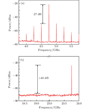 | Fig. 3. (a) Microwave spectrum of the photodetected pulse train after the first filter cavity via high-speed photodetector. The side modes are offset by 250 MHz from the 4.75 GHz are 27 dB below the peak. (b) The side-modes suppression at 23.75 GHz after the second filter cavity is approximately 43 dB. |
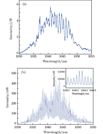 | Fig. 4. The comb output spectrum (linear scale) after the two filter cavities, respectively. The optical spectrum analyzer’ s resolution is set at about 5 GHz. (a) The spectrum with 4.75-GHz line spacing. (b) The spectrum with 23.75-GHz line spacing. To assess the mode feature of the spectrum, the inset figure is shown. |
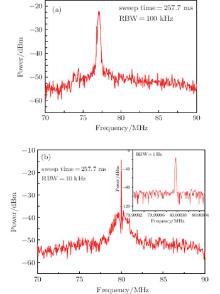
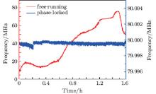
To attain the maximum resonance peaks, it was necessary to lock the frequency of the CW laser to one tooth of the comb with zero offset via an acoustic– optical frequency shifter (AOFS). A small output of LD laser was sent into the AOFS to shift the optical frequency in the range of 10 MHz at the center carrier frequency of 80 MHz. By frequency-shifting of the CW laser with this AOFS, and interfering with a mode of the comb, a beat signal was produced, as shown in Fig. 5. Free-running beat frequency was measured by a microwave spectrum analyzer with a 100-kHz resolution bandwidth, as shown in Fig. 5(a). By optimizing fast PID-locking settings, the external reference of 80 MHz was used to tightly lock the beat frequency between CW and one mode of the comb with servo bandwidth of ∼ 1 MHz, as shown in Fig. 5(b). The center peak corresponds to the 80-MHz shift frequency of AOFS. Shoulders around this peak indicate a locking bandwidth of about 1 MHz. The diode laser was thus locked to the comb with no offset. Once the beat frequency is locked to an external frequency reference, the beat frequency remains very stable for more than 1.5 hours, and the linewidth of the beat signal is reduced from MHz level to Hz level. Figure 6 illustrates the frequency fluctuations of the beat signal, recorded over 1.6 hours using a frequency counter (53132A Agilent Inc.) in 1-s gate time. The blue line represents the free-running beat signal. The red line is the 1045-nm CW laser, frequency is locked to one mode of the source comb; the resultant fluctuation of this beat frequency was better than that of the free-running beat signal. The output was stable enough, with a calculated RMS (root mean square) value of 0.0002%.
 | Fig. 5. (a) Free-running beat frequency between CW laser and one mode of the comb around 1045 nm, measured with a sweep time 4 ms (RBW: 100 kHz). (b) Beat frequency phase-locked to a reference synthesizer at 80 MHz (RBW: 10 kHz). The inset shows the peak with a strong signal-to-noise radio and a linewidth that is limited by the smallest instrumental resolution bandwidth of 1 Hz. |
 | Fig. 6. Time series of the stabilized beat frequency recorded over 1.6 hours with frequency counter. The red line is the free-running beat frequency. The blue line shows the beat signal phase-locked to the reference synthesizer at 80 MHz. |
In summary, a frequency comb based on a 250-MHz Yb:fiber comb is successfully created with two low-finesse filtering cavities in series. First, we simulated the side-mode suppression properties of double-FPC filtering schemes. Then, with the guidance of the numerical results, we experimentally realized a 23.75-GHz Yb-fiber comb by using two low-finesse Fabry– Pé rot cavities in series. The side-mode suppression rate is more than 43 dB, which is near the theoretical limit of 46 dB. In addition, by combining a 1030-nm narrow-linewidth CW laser, the absolute frequency of the astro-comb can be determined and the whole system can be stabilized. To achieve an astro-comb with a broadband optical spectrum covering the visible spectral range, we will use a spectral broadening technique in a further experiment.
| 1 |
|
| 2 |
|
| 3 |
|
| 4 |
|
| 5 |
|
| 6 |
|
| 7 |
|
| 8 |
|
| 9 |
|
| 10 |
|
| 11 |
|
| 12 |
|
| 13 |
|
| 14 |
|
| 15 |
|