

Power-induced polarization switching and bistability characteristics in 1550-nm VCSELs subjected to orthogonal optical injection*
[Chen Jian-Juna), b) , Xia Guang-Qionga) , Wu Zheng-Maoa)†  ]
]
]
|
|


Corresponding author. E-mail: zmwu@swu.edu.cn
Project supported by the National Natural Science Foundation of China (Grant Nos. 61178011, 61275116, and 61475127) and the Natural Science Foundation of Chongqing City, China (Grant No. 2012jjB40011).
The polarization switching (PS) and polarization bistability (PB) characteristics of a 1550-nm vertical-cavity surface-emitting laser (VCSEL) subjected to orthogonal optical injection are systematically investigated. The simulated results show that the PS and polarization-resolved nonlinear dynamical states of the VCSEL are critically dependent on the changing paths of the injected power. The polarization dynamics for different scanning directions of the injected power is presented to explain the polarization evolution during the formation of PS. In the case of forward scanning injected power, with the increase of frequency detuning level between the VCSEL and the injected light, the injected power required for PS gradually increases for negative frequency detuning but exhibits fluctuations for positive frequency detuning. In the case of reversely scanning injected power, the injected power required for PS displays fluctuant changes within the whole frequency detuning range. Specifically, PS may disappear under certain negative frequency detuning and large bias current. Furthermore, the hysteresis width as a function of the frequency detuning is calculated, and the regions for the appearance and disappearance of PB have been determined in the parameter space of the bias current and frequency detuning.
The nonlinear dynamics of semiconductor lasers (SLs) have wide applications in many fields such as optical chaos secure communication, high-speed random number generation, laser radar, photonic microwave generation, chaotic ultra-wideband signal generation, all-optical logic gates, etc.[1– 7] Recently, as one kind of SLs, vertical-cavity surface-emitting lasers (VCSELs) have received great attention due to their inherent advantages in comparison with edge-emitting lasers (EELs), such as reduced manufacturing costs, single-longitudinal mode operation, low power consumption, high compactness, high speed, circular output beam, etc.[8, 9] The emitted light of VCSELs is typically polarized along one of two orthogonal crystal axes due to the cylindrical geometry of the cavity with polarization anisotropy, and a small variation of bias current or device temperature may induce polarization instability. Especially, rich nonlinear dynamical behaviors can be generated by introducing one or more external degrees of freedom in VCSELs, [10– 25] where polarization switching (PS) and polarization bistability (PB) in a VCSEL have shown some promising applications, including all-optical logic gate, all-optical signal processing, and optical storage, and so on.[26– 31] Introducing optical injection is an effective technique to obtain PS and PB in VCSELs. It has been demonstrated that the polarization states of a free-running VCSEL can be controlled and switched by introducing orthogonal optical injection and appropriately choosing relevant parameters of the injected light. A configuration can be achieved by which a linearly polarized light from a tunable master laser is injected orthogonally to a free-running VCSEL.[23, 24]
For short-wavelength VCSELs emitting at 850 nm, the PS and PB under orthogonal optical injection have been investigated experimentally and theoretically.[32– 36] Recently, much more attention has been paid to exploring the PS and PB in long-wavelength VCSELs emitting at 1550 nm[37– 41] since 1550-nm VCSELs are power-efficient devices in local and access networks.[42] Generally, PS (PB) between two polarization modes of VCSELs under orthogonal optical injection can be classified as two main categories: one is wavelength-induced PS (PB) and the other is power-induced PS (PB). For the former, the relevant experimental and theoretical results have been reported in detail.[37– 40] However, as for the latter, although some experimental investigations have been conducted, [40, 41] the systematic theoretical researches are relatively inadequate.
In this work, by modifying the spin-flip model (SFM) of VCSELs to account for the noise and optical injection, the mappings of the polarization-resolved nonlinear dynamical states of a 1550-nm VCSEL subjected to orthogonal optical injection are calculated for forward and reversely scanning injected power in the parameter space of injected power and frequency detuning. Furthermore, power-induced PB widths, each as a function of frequency detuning, are simulated under different bias currents, and the regions for the appearance or disappearance of PB are also determined.
The spin-flip model (SFM), which was proposed by Miguel et al.[10] and Martin-Regalado et al., [11] has usually been employed to study the characteristics of VCSELs. For this model, a four-level system of the conduction and valence bands is considered in order to take into account the polarization properties of the laser electric field. The SFM can be extended to account for the injection of an external field with a linear polarization (LP) orthogonal to that of a free-running VCSEL. After referring to the relevant results in Ref. [41], a free-running 1550-nm VCSEL exhibits a dominant and stable y LP state (or “ parallel” polarization state) and a subsidiary x LP mode (or “ orthogonal” polarization state) over the whole bias current range. Therefore, in this work the optical injection from a tunable master laser is assumed to be along the x linear polarization direction. In this case, the rate equations of a 1550-nm VCSEL subjected to orthogonal optical injection can be written as


where subscripts x and y represent x and y LP modes, respectively, E is the slowly varied complex amplitude of the field, N is the total carrier inversions between the conduction and valence bands, n denotes the difference in carrier inversion between the spin-up and the spin-down radiation channels, k is the field decay rate, α is the linewidth enhancement factor, γ a and γ p are the linear anisotropies representing dichroism and birefringence, respectively, γ s is the spin-flip rate, β sp is the spontaneous emission factor, ξ + and ξ − are the Gaussian white noise terms of zero mean value, γ e is the decay rate of N, u is the normalized bias current, Einj is the amplitude of orthogonally injected field and Pinj = ❘ Einj❘ 2 represents the orthogonally injected optical power, η inj is the injection coefficient, ν inj is the frequency of injected light, and ν 0(= (ν x+ ν y)/2 (ν x and ν y are the frequencies of the x and y linear polarizations, respectively) is the central frequency of the VCSEL. Considering the fact that the polarization state of the injected light is only in the x LP mode as mentioned above, we use Δ ν x(= ν inj − ν x) to represent the frequency detuning.
The rate equations (1)– (4) can be numerically solved by the fourth-order Runge– Kutta method. During the calculation, the integration time step is 1 ps, and the used parameters are as follows:[41]γ e = 1 ns− 1, γ p = 192.1 ns− 1, γ a = 1 ns− 1, γ s = 1000 ns− 1, α = 3, k = 300 ns− 1, and β sp = 10− 6.
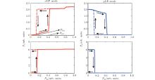
Figure 1 shows the variations of polarization-resolved output powers of x and y LP modes with injected optical power by increasing and reducing injected optical power Pinj with frequency detuning Δ ν x = − 9 GHz under two different bias currents (u = 3 and u = 7). As shown in the upper row, for a relatively small bias current, with the increase of Pinj from zero, PS will occur abruptly between x and y LP modes at a specific value of Pinj1, where the output of x polarization mode is switched from an off-state to an on-state, meanwhile the output of y polarization mode experiences an opposite process with an extremely high extinction ratio. When Pinj continuously decreases from above the specific value Pinj1, PS can also be observed at another specific value of Pinj2, which is lower than Pinj1. For different scanning paths of Pinj, the different injected optical powers that are required for PS lead to the appearance of a hysteresis cycle, i.e., polarization bistability (PB) occurs. However, for a large bias current, as seen in the lower row, PS can be observed during an increase of the injected power from zero but does not occur during a decrease of the injected power.
 | Fig. 1. Polarization-resolved output powers of x LP (left column) and y LP (right column) modes for increasing (solid lines) and decreasing (dotted lines) injected optical power Pinj with Δ ν x = − 9 GHz, where the upper row is for u = 3 and the lower row is for u = 7. |
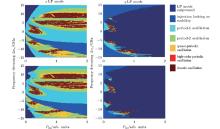
The above results show that there exists a bistable region, where a fixed injection power is located, and that the polarization-resolved output of the VCSEL depends on the path of varying injected power. Next, we will analyze the influence of the variation path of injection power on the polarization-resolved dynamical state of the VCSEL output. Figure 2 displays the mappings of polarization-resolved dynamical states under forward (upper row) and reverse (lower row) scanning injected power for u = 3 with different values of frequency detuning Δ ν x. Here, the polarization dynamics is determined by calculating the number of different successive extrema of the polarization-resolved output time series.[34] Due to the extremely high extinction ratio of PS corresponding to y LP mode, the PS points can be clearly identified. In the right column of Fig. 2, the region shown by black blue (the first color on the far right side of Fig. 2) corresponds to the scenario where the y LP mode is completely suppressed. Therefore, the left boundary of this color marks the PS points. As seen from these figures, the y LP mode behaves as diverse dynamical states near the PS boundary, such as stable state, period 1, period 2, quasi-period, high-order periodic, and chaotic oscillations. Comparing this with the case of forward scanning of the injected power, the Pinj required for PS is lower under the reverse scanning of the injected power in some frequency detunings, which is the reason for the occurrence of PB the hysteresis cycle. In the left column of Fig. 2, the x LP mode is locked in frequency and polarization to the master laser only for the case of negative frequency detuning, which is bounded by the Hopf bifurcation in the upper region and by saddle-node bifurcation in the lower region. This asymmetric feature of the injection locking region originates from the fact that the parameter α has a positive value in VCSELs.[23] Besides, there is a chaotic region under small positive detunings and injected powers, which is very close to the PS boundary and exhibits complex polarization dynamics for these two LP modes. For relatively large positive detunings, broader chaotic regions emerge after the PS, where only the x LP mode is lasing. Furthermore, by carefully comparing the mappings of polarization-resolved dynamical states obtained by different varying paths, it can also be seen that there is a bistability of the dynamical state.
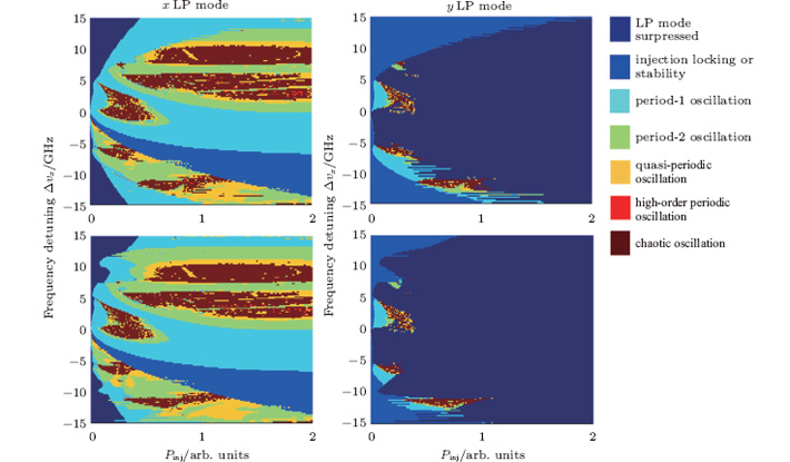 | Fig. 2. Mappings of polarization-resolved dynamical states each as a function of injection power Pinj and frequency detuning Δ ν x for increasing (upper row) and decreasing (lower row) injection power under u = 3, where the different colors represent different dynamical states. |
For different bias currents, the dependences of Pinj required for PS on frequency detuning Δ ν x are shown in Fig. 3, where Figs. 3(a) and (3(b)) correspond to the case of increasing (decreasing) Pinj. As shown in Fig. 3(a), with the increase of negative frequency detuning level, the overall variation tendency of Pinj required for PS increases with slight fluctuations. When the frequency detuning Δ ν x is close to − 1 GHz, Pinj required for PS reaches a minimum value. As for the positive frequency detuning, as the level of the positive frequency detuning increases, the injected power for PS increases at first, it reaches an extreme value, and it then decreases through a minimum and finally increases gradually. It is worth mentioning that the minimum will shift towards a larger positive frequency detuning with an increase of the bias current. Figure 3(b) is a case where Pinj continuously decreases. Compared with the scenario in Fig. 3(a), the overall variation tendency of Pinj required for reverse PS exhibits more fluctuations. It should be particularly pointed out that if the applied bias current is too large, then the reverse PS will not appear within a certain frequency detuning range. In addition, the frequency detuning range for the disappearance of reverse PS is dependent on the bias current, which is in a range of − 8 GHz– 0.5 GHz under u = 5 but − 10 GHz– 0.5 GHz under u = 7.
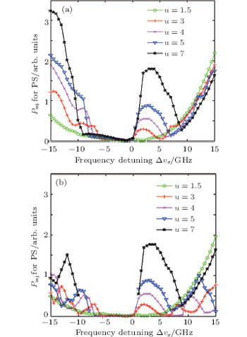 | Fig. 3. Plots of Pinj required for PS versus frequency detuning Δ ν x for increasing (a) and reducing (b) the injected power fordifferent values of the bias current u. |
Figure 4 shows the variations of calculated hysteresis width Δ P with Δ ν x for different values of bias current u. As shown in this figure, relatively large fluctuations of the hysteresis width can be observed for a large negative frequency detuning range. However, for a large positive detuning range, the hysteresis width will increase monotonically. For a relatively small frequency detuning level, the hysteresis width Δ P is about 0 and PB will disappear since the results obtained by forward scanning and reversely scanning the injected power are approximately equal (as shown in Fig. 3). For different bias currents, the frequency detuning ranges for the disappearance of PB are different.
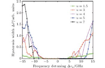 | Fig. 4. Variations of hysteresis width with frequency detuning for different bias currents. |
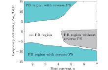
Finally, the distribution of hysteresis regions in the parameter space of the frequency detuning and the bias current is displayed in Fig. 5. As shown in this figure, with the increase of the bias current, the PB region is shifted gradually towards a larger frequency detuning level. When the frequency detuning is limited within a range from − 15 GHz to 15 GHz, the PB region with reverse PS that is located in a positive frequency detuning range shrinks much faster than that located in a negative frequency detuning range. For u > 5.5, the PB region with reverse PS completely disappears in the positive frequency detuning range while it remains in the negative frequency detuning range. Additionally, for u > 4.4, a PB region without reverse PS appears and gradually extends with the increase of the bias current. The above results illustrate that the characteristics of PS and PB in 1550-nm VCSELs subjected to orthogonal optical injection can be controlled through adjusting the bias current and frequency detuning.
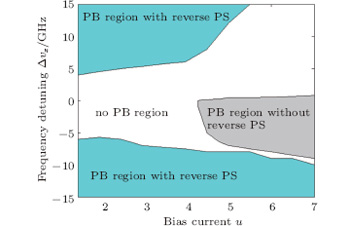 | Fig. 5. Hysteresis regions each as a function of frequency detuning and bias current. |
In this paper, power-induced PS and PB characteristics in 1550-nm VCSELs subjected to orthogonal optical injection are investigated by using the extended SFM model. The polarization-resolved output power and the dynamical states of 1550-nm VCSELs are dependent on the scanning path of the injection optical power, and bistability of the output power and the dynamical state have been observed. With the increase of frequency detuning level, the overall variation tendency of Pinj required for PS increases slightly with fluctuation under negative frequency detuning but the Pinj required for PS shows an extreme value and a minimal value under positive frequency detuning. Through adjusting the bias current or frequency detuning, the characteristics of PS and PB in 1550-nm VCSELs subjected to orthogonal optical injection can be controlled.
| 1 |
|
| 2 |
|
| 3 |
|
| 4 |
|
| 5 |
|
| 6 |
|
| 7 |
|
| 8 |
|
| 9 |
|
| 10 |
|
| 11 |
|
| 12 |
|
| 13 |
|
| 14 |
|
| 15 |
|
| 16 |
|
| 17 |
|
| 18 |
|
| 19 |
|
| 20 |
|
| 21 |
|
| 22 |
|
| 23 |
|
| 24 |
|
| 25 |
|
| 26 |
|
| 27 |
|
| 28 |
|
| 29 |
|
| 30 |
|
| 31 |
|
| 32 |
|
| 33 |
|
| 34 |
|
| 35 |
|
| 36 |
|
| 37 |
|
| 38 |
|
| 39 |
|
| 40 |
|
| 41 |
|
| 42 |
|