

A novel method of evaluating large mode area fiber design by brightness factor*
[Zhang Hai-Taoa)†  , Chen Dan
b) , Ren Hai-Cuia) , Yan Pinga) , Gong Ma-Lia)‡ ]
, Chen Dan]
|
|


Corresponding author. E-mail: zhanghaitao@mail.tsinghua.edu.cn
Corresponding author. E-mail: gongml@mail.tsinghua.edu.cn
Project supported by the National Natural Science Foundation of China (Grant No. 61475081)
A novel evaluation term and a more reasonable criterion, which is described by a new parameter of brightness factor for active large mode area fiber design, are presented. The brightness factor evaluation method is based on the transverse mode competition mechanism in fiber lasers and amplifiers. The brightness factor can be seen as a description of fiber general property since it can represent the output laser brightness of the fiber laser system and because of its ability to resist the nonlinear effect. A core-doped active large pitch fiber with a core diameter of 190 μm and a mode-field diameter of 180 μm is designed by this method, and the designed fiber allows effective single-mode operation.
Fiber lasers with high power, excellent beam quality, and high efficiency are increasingly being developed for many applications and in many areas such as industry, medicine, communication, military, and research. The average output power has been scaled beyond the ten kilowatt level, maintaining a near-diffraction-limited beam quality.[1] However, scaling the pulse energy and peak power of fiber lasers is more challenging. The peak power and energy level are limited by nonlinear effects, such as stimulated Raman scattering (SRS) and stimulated Brillouin scattering (SBS) due to the high optical intensity and long interaction length in the fiber.[2, 3] Scaling to larger effective mode-field-diameter (MFD) helps reduce the optical density and the effective working length of the fiber with the same ytterbium or other rare-earth dopants because raising the core size leads to the increase of the core-to-cladding ratio and the pumping absorption efficiency increases. For step-index fibers, prominent techniques for effective single-mode operations include matched excitation by particularly ion-doping, [4] and higher-order mode (HOM) discrimination by bending[5] or by filtering through high loss waveguide structure, such as a chirally coupled core.[6] However, these methods have limited effective MFD scalability because the mode propagation coefficients of the normal step-index fibers with core sizes beyond 50 μ m will become too densely packed to discriminate between the fundamental mode and its nearest neighbors.[7]
Novel very large mode area (VLMA, core diameter beyond 50 μ m) active fibers have been developed to provide mode scaling, such as semi-guiding high-aspect-ratio-core (SHARC) fibers, [8] gain-guided, index-antiguided fibers, [9] and photonic crystal fibers (PCFs).[10] In theory, the SHARC structure implies nearly unlimited effective MFD scalability but it has a multimode beam quality in the slow-axis direction. In addition, the gain-guided, index-antiguided fiber is quite challenging to obtain high pump efficiency due to the leaky cladding. Among them, the active PCF, especially the large pitch fiber (LPF) structure with pitches 10 times larger than the wavelength, seems to be one of the most promising approaches for a core diameter beyond 100 μ m.[10– 13] In LPF mode area scaling studies, the fiber designs are usually guided in terms of transversal mode discrimination, [14, 15] i.e., differential propagation losses between modes, especially the mode discrimination of the fundamental mode (FM) and the first HOM.
However, in fiber laser system we are more concerned with the laser performance of the VLMA-active LPF in the high power dynamic mechanism than in a simple passive waveguide mechanism. Hence, in this paper, we present a novel evaluation term and a reasonable criterion for active LPF designs for laser applications. We define a novel parameter γ , brightness factor, as the evaluation term. The brightness factor is defined as the product of output laser brightness in unit pump power and the square of effective MFD (proportional to mode field area) and it has no dimension. Therefore, the brightness factor γ allows one to take all factors into consideration on fiber designs, including the effective MFD, laser beam quality, and conversion efficiency of the output beams. A higher value of the brightness factor γ of the VLMA fiber laser indicates a higher output laser brightness, and the higher mode area means that it has a higher ability to resist the nonlinear effect. In conditions of enlarged MFD, in order to obtain the output beam brightness (relating to the efficiency and beam quality with unit pump power) of the fiber laser with unit power, we need not only investigate the mode discrimination in the propagation process, as shown in Refs. [14] and [15], but should also study the transverse mode competition along the fiber in the amplification process. The best structure with respect to each core-diameter value is the one in which the brightness factor achieves a maximum value. Unlike the optimization method that is commonly adopted in LPF design, which is to find the maximum loss difference by a fixed FM loss, this optimization method requires the maximum brightness factor. The brightness factor can integrate many design methods, making this method suitable not only for the LPF fiber but also for the design of other fiber structures.
In this paper, we first introduce the calculation of brightness factor and present the LPF structure design procedure using the maximum brightness factor as a criterion. In order to compare with the design result of fixed FM loss, the core diameter is selected as 51 μ m, which is the same as the value in Ref. [14]. We then conduct further design with LPF of larger core size by the brightness factor method. Finally, as an example of the extension and application of the brightness factor evaluation method (BFEM), a Yb-doped LPF with the largest core diameter of 190 μ m and an effective MFD of 180 μ m is designed.
As shown in Fig. 1(a), all of the Yb-doped PCFs considered in this paper have two rings of hexagonally arranged air holes with the core formed by one missing air-hole because this kind of structure can offer the highest mode discrimination between FM and first HOM combined with an FM having a moderate loss of beam quality.[14] The hole-to-hole distance (Γ ) and the normalized hole-diameter (d/Γ ) determine the properties of the LPFs, such as propagation loss, single-mode regime, and effective mode area. To optimize the structure of an LPF with a fixed core diameter, the normalized hole size is modified. The mode profiles and the propagation losses due to leakage are calculated by a mode solver based on the finite element method (FEM).
 | Fig. 1. The LPF schematic model, showing (a) the cross section of the LPFs, and (b) the laser cavity and the amplifier. |
However, in addition to the eigenmode propagation characteristics, we are more concerned with the laser performance of the active LPF in the high-power dynamic mechanism. The dynamic mode analysis of the LPF laser utilizes the typical linear cavity as described schematically in Fig. 1(b). The signal powers of each mode and the pump power are given by the following space-dependent and time-independent steady-state rate equations:[16]


where τ is the spontaneous lifetime of the upper lasing level; h is the Planck constant; ν s and ν p are the laser and pump frequencies, respectively; N2 and N1 are the population densities of the lower and upper lasing levels; N0= N1 + N2 is the doping concentration distribution; 


Additional boundaries are needed to solve the coupled differential Eqs. (1)– (3), the boundary conditions on both sides are given by

where L is the fiber length; R1 and R2 are the reflectivities of the reflectors at z = 0 and z = L, respectively. Rate equations (1)– (3) along with boundary conditions (4) are iterated with the value of the output power 

In the fiber laser system, the brightness of a laser is used to describe its ability to produce the highest power in the smallest spot and the smallest divergence. The brightness of a low diverging laser source for the circular case is described as B = Ptotal/(M2λ )2 = Ppη /(M2λ )2, [17] where λ is the laser wavelength. For VLMA fibers, the ability to resist nonlinear effect is another criterion to qualify fiber performance, which is related to the power density. When the laser brightness in the unit pump power meets the requirement, the larger the mode area, the stronger the ability to resist nonlinear effect will be. With both desirable factors, including high brightness and high nonlinear effect resistance, taken into consideration, we propose a new parameter of brightness factor γ for the characterization of laser beams. This is defined as

where η /(M2λ )2 denotes the output laser brightness in unit pump power. Brightness factor has instructive meaning in two aspects. (i) When the MFD of FM is fixed, the higher the output laser brightness in unit pump power is, the higher the pump conversion efficiency and the better focus intensity of the fiber laser will be. (ii) When the laser brightness is fixed, the larger the MFD of FM is, the smaller the power density will be, which can effectively resist nonlinear effect for high peak power pulses. The brightness factor can represent the output laser brightness of fiber laser system and its ability to resist nonlinear effect, therefore it can be seen as a description of the fiber's general properties. For VLMA fibers, the higher the brightness factor γ is, the better the properties of the fiber will be. This is a more reasonable criterion for active LPF designs.
By substituting the filling factor and loss of each mode inside the doped core into the rate equations, we can obtain the mode competition result and power weights. We can then calculate conversion efficiency of the output beam by η = Ptot/Ppump. The corresponding effective MFD of FM can be defined as deff = 2∬ I(x, y)dxdy/(π ∬ I2(x, y)dxdy)1/2[7] and the beam quality factor (M2) can be calculated by the method presented in Ref. [18]. Thus, the brightness factor γ of the output beam is obtained. The highest brightness factor is the best output beam property which corresponds to the optimal d/Γ .
As shown in Fig. 1(a), the core diameter (dcore) can be obtained by dcore = 2Γ − d. Thus, when the core diameter is fixed, only the optimal d/Γ is needed to determine the best structure of the LPF. Using the BFEM presented above, we optimize the structures of the LPFs with core diameters varying from 51 μ m to 190 μ m.
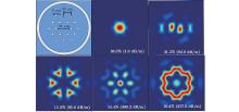
Firstly, we simulate the mode profiles and the propagation losses of LPFs with a fiber core diameter of 51 μ m and various values of d/Γ (dcore = 2Γ − d). The proportion of the inner cladding diameter to the core diameter maintains 3.15 since this is a reasonable structure, as presented in Ref. [17]. This inner-cladding size can make sure the small-signal pump absorption coefficient is larger than 3 dB/m. As shown in Fig. 2, we use the design of an LPF with a normalized hole-diameter of 0.3 to illustrate the eigenmode simulation process and the results obtained by FEM. The loss of FM is 1 dB/m and the first HOM deformation is 81 dB/m, which are in accordance with those in Ref. [14], showing the correctness of the method we used. In the case that the core diameter and the other parameters are fixed, we consider a 1.2-m-long Yb-doped fiber laser which is pumped at 975 nm with 200-W forward pump power. The laser wavelength (λ s) is 1040 nm. Γ or LPFs with a core diameter of 51 μ m, the output beam effective MFD and the M2 of LPF lasers versus the values of d/Γ are shown in Fig. 3(a). With the increase of d/Γ , the MFD of the output beam declines until d/Γ ≥ 0.39. The d/Γ = 0.39 is an inflection point. The variation trend of the beam quality factor is similar to that in the case of the effective MFD.
 | Fig. 2. Calculated modal intensity profiles of an LPF (d/Γ = 0.3, dcore = 51 μ m; ), the corresponding overlap of the mode field with the core area and the propagation losses (ordered by decreasing doping overlap). |
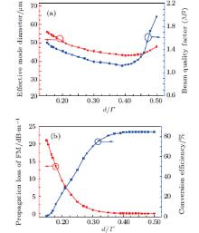
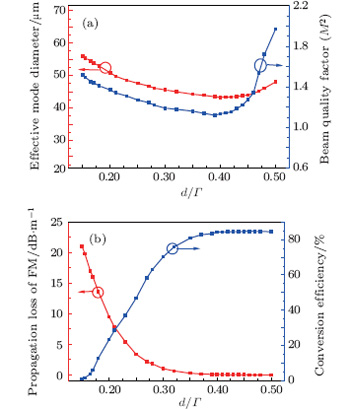 | Fig. 3. (a) Effective MFD and M2 and (b) propagation loss and optical– optical conversion efficiency versus d/Γ of the FM with dcore = 51 μ m. |
As presented in Fig. 3, the optimal effective MFD, M2 of the output laser and the conversion efficiency correspond to different values of optimal d/Γ . As a result, each single parameter cannot reveal the property of the LPF laser accurately. Therefore, the brightness factor γ , which synthesizes all the three parameters, is used to find out the optimal d/Γ . The first HOM discrimination and the brightness factor γ of unit spectral width versus the d/Γ are shown in Fig. 4. The brightness factor γ reaches its highest value when d/Γ = 0.39 where the first HOM discrimination is 21 dB/m. Our study indicates that the optimal d/Γ for LPFs with the core diameter of 51 μ m is 0.39, which can reduce the loss of FM to 0.08 dB/m while remaining near diffraction-limited beam quality, differing from the result of Ref. [14] in the respect that the optimal d/Γ is 0.3 when the loss of FM is 1 dB/m and the first HOM discrimination is 81 dB/m for the same core size fiber. Thus, it can be seen that the LPF structure optimized by BFEM has a smaller mode loss, which can improve the conversion efficiency and the laser brightness.
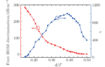 | Fig. 4. The firt HOM discrimination and the brightness factor γ versus d/Γ with dcore = 51 μ m. |
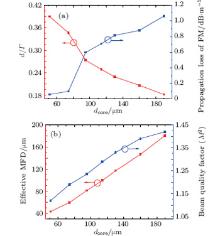
According to the BFEM presented above, in the simulations below we optimize the structures of the LPFs with core diameters varying from 51 μ m to 190 μ m. The inner guiding structure (the pitch and the d/Γ ) is modified, and the Yb-doped area of each fiber is equal to the mode-field-area. We use the fiber amplifier system since the VLMA fibers are generally applied to the amplifier system. The optimal d/Γ and the FM propagation loss of LPF versus dcore diameter are shown in Fig. 5(a). It can be seen that the larger core diameter requires a smaller d/Γ to obtain the highest brightness factor, leading to a high leakage of the FM. The FM loss of the 190-μ m core size LPF is around 1 dB/m, which is a reasonable value for a short high power fiber amplifier.
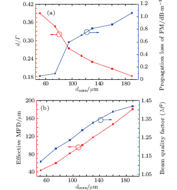 | Fig. 5. (a) Optimal d/Γ and the propagation loss and (b) effective MFD and M2 versus dcore. |
To describe the behaviors of all modes in the amplification process, we assume that all of the modes have the same signal power, which usually represents the case of the worst input beam quality. The signal power of each mode is 10 W and the forward pump power is 500 W. The output beam properties of each amplifier are shown in Fig. 5(b). It is shown that the effective MFD of the output laser beam tends to linearly increase with the augment of the fiber core diameter, directly resulting in the enlargement of the threshold of the nonlinear effect. The beam quality factor M2 rises slightly due to the reduction of d/Γ . A large effective MFD of 180 μ m with excellent near diffraction-limited beam quality (M2 ≈ 1.4 ) is achieved when the core diameter is 190 μ m.
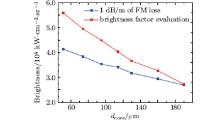
As shown in Fig. 6, we further design the LPFs in terms of mode discrimination with a fixed FM loss of 1 dB/m, as presented in Ref. [14], and make a comparison of laser brightness in unit pump power between these two design criteria. We can see that the LPF with a core diameter less than 190 μ m can obtain higher laser brightness when evaluated by using the brightness factor. This is because the FM loss of the LPF designed by the BFEM is less than 1 dB/m, thus improving the conversion efficiency. In addition, the laser beam quality is a little better. The comparison illustrates the advantage of the BFEM. The BFEM considers the mode competition which conforms to the actual working mechanisms of the laser and amplifier. Improving the fiber laser brightness and improving the ability to resist nonlinear effect are its goals. The BFEM is suitable for designing other kinds of large mode area rare-earth doped fibers.
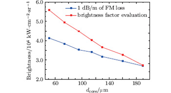 | Fig. 6. Comparison of the laser brightness in unit pump power between two design criteria. |
In this paper, a novel evaluation term and a reasonable criterion, which is described by a new parameter of brightness factor for active large pitch fiber design, are proposed. The BFEM is based on the transverse mode competition in the LPF laser and it synthesizes the effective MFD of FM, laser beam quality, and conversion efficiency of the output laser beams. The structures of the LPFs with core diameters varying from 51 μ m to 190 μ m are optimized. The LPF optimized by BFEM can ensure that the loss of the FM is less than 1 dB/m. The laser brightness decreases with the fiber core size due to the rising FM loss. An LPF with very large core size (core diameter of up to 190 μ m) is designed, allowing for very large mode diameter (180 μ m) at high average power with near diffraction-limited beam quality.
| 1 |
|
| 2 |
|
| 3 |
|
| 4 |
|
| 5 |
|
| 6 |
|
| 7 |
|
| 8 |
|
| 9 |
|
| 10 |
|
| 11 |
|
| 12 |
|
| 13 |
|
| 14 |
|
| 15 |
|
| 16 |
|
| 17 |
|
| 18 |
|