Xu Dan, Wang Xiao-Yun†, Huang Yong-Gang, Ouyang Shi-Liang, He Hai-Long, He Hao. Position-dependent property of resonant dipole—dipole interaction mediated by localized surface plasmon of an Ag nanosphere* . Chinese Physics B, 2014, 24(2): 024205
Permissions
Position-dependent property of resonant dipole—dipole interaction mediated by localized surface plasmon of an Ag nanosphere*
Xu Dan, Wang Xiao-Yun†, Huang Yong-Gang, Ouyang Shi-Liang, He Hai-Long, He Hao
College of Physics, Mechanical and Electrical Engineering, Jishou University, Jishou 416000, China
Project supported by the National Natural Science Foundation of China (Grant Nos. 11347215, 11464014, and 11104113), the Natural Science Foundation of Hunan Province, China (Grant Nos. 13JJ6059 and 13JJB015), and the Natural Science Foundation of Education Department of Hunan Province, China (Grant Nos. 13C750 and 13B091).
Abstract
We use the photon Green-function method to study the quantum resonant dipole–dipole interaction (RDDI) induced by an Ag nanosphere (ANP). As the distance between the two dipoles increases, the RDDI becomes weaker, which is accompanied by the influence of the higher-order mode of the ANP on RDDI declining more quickly than that of the dipole mode. Across a broad frequency range (above 0.05 eV), the transfer rate of the RDDI is nearly constant since the two dipoles are fixed at the proper position. In addition, this phenomenon still exists for slightly different radius of the ANPs. We find that the frequency corresponding to the maximum transfer rate of RDDI exhibits a monotonic decrease by moving away one dipole as the other dipole and the ANP are kept fixed. In addition, the radius of ANP has little effect on this. When the two dipoles are far from the ANP, the maximum transfer rate of the RDDI takes place at the frequency of the dipole mode. In contrast, when the two dipoles are close to the ANP, the higher-order modes come into effect and they will play a leading role in the RDDI if they match the transition frequency of the dipole. Our results may be used in a biological detector and have a certain guiding significance for further application.
The effect of an electromagnetic field on the radiation property has been completely investigated and sorted into quantum electrodynamics (QED), which is based on the prediction that the spontaneous emission rate could be tailored by using the electromagnetic environment that was developed by Purcell.[1] The characteristics of QED have been studied in both theory and experiment, and a variety of QED devices have been proposed and developed by many researchers.[2– 8] Some novel concepts, such as enhanced and inhibited spontaneous emission, [5, 8] reversible spontaneous emission, [6] and the one-atom maser, [9] have been well known.
The quantum RDDI can be highly modulated by the electromagnetic environment. Two two-level atoms, one is excited and the other stays in the ground state, can interact with each other by exchanging a photon. A photon emitted by the excited atom can be absorbed by the other atom in the ground state. The transfer rate of the RDDI and the RDDI potential energy is determined by the rates of photon emission, transmission and absorption. A variety of electromagnetic environments have been used to control and modify these characteristics, such as a vacuum, [8, 10] optical cavities, [11, 12] photonic materials, [13] and metal surfaces, [14, 15] and so on. For example, a metal surface can concentrate light into a nanoscale spatial region near the metal/dielectric interface by the excitation of surface plasmons (SPs). This ability can extremely enhance the rates of photon emission and absorption. In particular, by rationally designing and optimizing geometry, the metallic structures can be beneficial to collecting the emitted photons from one dipole and transferring them to the other dipole efficiently.
Metal nanosphere (MNP) is a promising platform to investigate the quantum RDDI, where they induce the localized surface plasmon resonances (LSPRs) under light illumination. A surface plasmon polariton (SPP)-based waveguide is a potential candidate for guiding light due to its ability to achieve the nanoscale confinement of an incident optical field in two dimensions. As a result, it has been regarded as a building block for the novel ultracompact photonic device and integrated circuit.[16] Up to now, large numbers of SPP-based waveguiding structures have been investigated, including hybrid plasmonic waveguides, [17] metal stripes embedded in homogeneous dielectrics, [18] metallic nanowires, [19] metal slots, [20] etc. However, SPP-based waveguides can only confine light in two dimensions. In contrast, LSPRs from an MNP can concentrate the optical energy in three dimensions and thus find a wide application prospect in integrated plasmonic circuits, for instance, an LSPR-based sensor, an SP-based photoswitch, and an SP-based laser.[21] All these applications benefit from the extremely amplified and tightly confined local field, which leads to an ultra-small mode volume that significantly increases the light-matter interaction. Based on this unparalleled ability, the MNP is expected to remarkably improve the photon emission and absorption rates of the two nearby dipoles, as well as the RDDI between them.
Recent studies show that this kind of interaction has been applied to implement quantum entanglement preparation and quantum information processing, [15, 22– 28] cooperative radiation, [29] Fö rster energy transfer, [30, 31] dipole nanolasers, [32] etc. Furthermore, some novel quantum phenomena have been found.[33– 35] All of these applications and phenomena mentioned above are related in essence to the transfer rate or RDDI potential energy.
In previous theoretical studies, the transfer rate and the RDDI potential energy are obtained by numerical methods[15, 24, 35– 38] or analytic methods.[39– 43] For numerical methods, an independent program needs to sweep the parameters for the dipoles at different positions or with different polarizations, where a single run usually needs considerable computational resources for the finite element method (FEM) or the finite-difference time-domain (FDTD) method. However, for a relatively simple electromagnetic environment, such as the structure of an ANP, we can treat the problem by using the analytical Green function.[44]
The Green function G (r, r′ ; ω ) describes the propagation of photons from the source point (r′ ) to the point (r) with an angular frequency (ω ). It includes all of the possible scattering events and the information about the probability that a photon will arrive at a particular location for a given excitation source. The transfer rate and the RDDI potential energy can be expressed by the Green function. Here, we adopt the analytical Green function approach to investigate the quantum RDDI mediated that is by the LSPR of an ANP.
In this work, we systematically analyze the quantum RDDI induced by an ANP. Firstly, we examine the effect of the ANP on the spontaneous emission rate which determines the strength of the corresponding transfer rate. We find that as the distance between the quantum dot (QD) and the surface of the ANP is increased, the spontaneous emission rate decreases and the effect of ANP higher-order mode dominates compared with that of the dipole mode. We then further study the effect of the distance between the two QDs on the transfer rate of the RDDI by fixing one QD at x axis and change the position of the other one along x axis, here we consider the two QDs that are on the same side of the ANP. We find that the transfer rate of the RDDI nearly keeps constant in a broad frequency range for a set of ANPs with a slightly different radius. In addition, the frequency corresponding to the maximum of transfer rate of RDDI shows a monotonic decrease as the distance between QD and ANP is increased. Finally, we consider two general cases where one QD is fixed far from or nearly touches the surface of the ANP. We investigate the property of the transfer rate by changing the location of the other QD on the same plane. It is shown that the dipole mode of the ANP makes a main contribution to the transfer rate of RDDI when the QDs are far from the ANP. While the QDs are close to ANP, the higher-order modes may be the major factors depending on the transition frequency of the dipole.
2. Model and solution
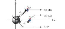
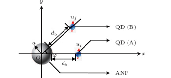
A schematic diagram of the system is illustrated in Fig. 1. An ANP with radius a is located at the origin. QD (A) is located at the x axis with a distance of da from the surface of ANP, and ui is its transition dipole moment. QD (B) is fixed on a line with the angle φ included between the line and x axis, its distance is db from the surface of the ANP and uj is its transition dipole moment.
Fig. 1. Schematic diagram of the system for the coupled QD-ANP system.
According to Refs. [31] and [44], the transfer rate and the potential energy of the RDDI in the quantization scheme are
where i and j represent QD (A) and QD (B), respectively, Γ ij and δ ij are the transfer rate and potential energy of the RDDI, respectively, ri and rj refer to their spatial positions, ω refers to the transition frequency, ɛ 0 is the vacuum permittivity, ħ is the Planck constant, and G(ri, rj, ω ) is the Green tensor. The Green function in a medium with ɛ (r, ω ) (complex dielectric constant) and μ = 1 is given as[45, 46]
where k0 = ω /c, ω is the angular frequency and c refers to the speed of light.
For these calculations, we use an established analytical approach where the Green function is expanded in spherical vector functions.[43, 46] The specific expressions are given in Appendix A.
3. Discussion
On the basis of the above results, we can analyze the transfer rate (Γ ij) and potential energy (δ ij) of the quantum RDDI. QDs A and B are located at the x axis with the distances of da and db from the surface of ANP, respectively, the transition dipole moment ui is equal to uj and radius of ANP is a. According to Refs. [25] and [26], we can easily obtain(Γ ii and Γ jj are the spontaneous emission rate). We first investigate the effect of the ANP on Γ ii which determines the maximum strength of Γ ij. Here, we set a = 20 nm and study the effect of distance d between the QD and the surface of the ANP on Γ ii.
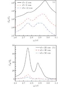
The normalized spontaneous emission rate (Γ ii/Γ 0) is shown in Figs. 2(a) and 2(b) corresponding to the small and large d, respectively. Γ 0(ω ) = u2ω 3/3π ɛ 0ħ c3, where Γ 0 is the local coupling strength for a two-level atom at transition frequency ω of the bare atom in vacuum and u is the transition dipole moment. From Fig. 2(a) it follows that Γ ii exhibits three main peaks. As explained by Hughes, [24] the peak of Γ ii at the lowest frequency is caused mainly by the dipole mode while the other peaks at higher frequencies arise from the higher-order modes. As d is increased, Γ ii becomes weak and the peak of the ANP′ s dipole modes on Γ ii decreases more slowly than that of the higher-order modes. For example, when d = 2 nm, the values of Γ ii are above 1.9× 10⁵ and 7.5× 10³ at the frequencies of the ANP′ s higher-order mode and dipole mode, respectively. While d = 6 nm, the values of Γ ii decrease to 4600 and 1300 for these two modes respectively. It is noted that as d is 12 nm, the higher-order mode and the dipole mode have equally contributed to Γ ii. It is natural that the contribution of the higher order mode is suppressed by the dipole mode when d = 12 nm, which is shown in Fig. 2(b). In particular, when d = 50 nm, Γ ii at the frequency of the ANP′ s dipole mode is ten times than that of the higher-order mode. The above result shows that the strength of Γ ii is attributed mainly to the dipole mode when the QD is far from the surface of ANP. In addition, we find that the normalized spontaneous emission rate is less than five for d > 50 nm.
In contrast, the higher-order mode plays a dominant role and dramatically enhances the spontaneous emission rate when QD is close to the surface of ANP. Therefore, we set da = 2nm and investigate the db-dependent Γ ij and δ ij. The other parameters are the same as those mentioned previously.
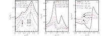
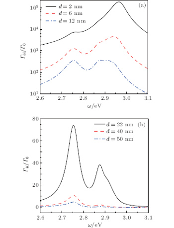
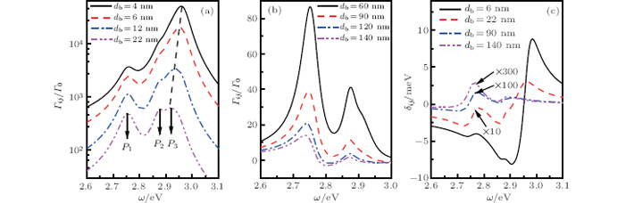
The influence of db on Γ ij is shown in Figs. 3(a) and 3(b)for the small and large values of db, respectively. There exists three main peaks for Γ ij, which are marked as P1, P2, and P3, as shown in Figs. 3(a). It is clear that as db is increased, the Γ ij decreases and shows a much stronger downtrend for the ANP′ s higher-order modes than for the dipole mode. For example, when db changes from 4 nm to 6 nm, Γ ij/Γ 0 varies from 5.1× 10⁴ to 2.02× 10⁴ at the frequency of P3, while Γ ij/Γ 0 decreases from about 3600 to 2400. In addition, we find that Γ ij has similar values at frequencies of P1, P2, and P3 when db = 22nm. Figure 3(b) shows a similar tendency of Γ ij/Γ 0 to Fig. 3(a). We find that the influences of the higher-order modes of the ANP on Γ ij can be ignored when db > 120nm. Moreover, the dipole modes dominate Γ ij when the QDs are far from the surface of the ANP.
Fig. 2. Normalized spontaneous emission rate Γ ii/Γ 0 versus frequency ω for the distance between the QDs and the surface of the ANP d = 2, 6, 12 nm (a), and 22, 40, 50 nm (b).
The potential energy of the DDI (δ ij) is shown in Fig. 3(c). The dipole moments of the two dipoles are both set to be 24 D (1 D = 3.33564× 10− 30 C · m), which is comparable to the dipole moment used in other studies.[39] It is obvious that the numeric values of δ ij are relatively small and δ ij drops steeply as db increases. For instance, δ ij ≤ 8.817meV when db is 6 nm, δ ij ≤ 0.016 meV as db is 90 nm, and δ ij ≤ 0.009meV while db is 140 nm. It is found that δ ij is relatively small when db = 22nm, which is beyond the scope of this work.
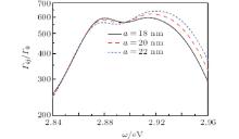
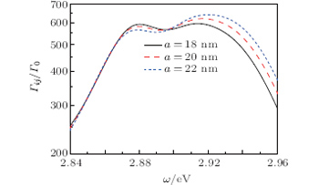
Figure 3(a) shows that the higher-order modes play the main role in RDDI for relatively small db. It becomes more and more weak as db is increased. We find that over a broad frequency range (the plateau region between P2 and P3) the Γ ij nearly keeps constant for the case of db = 22nm. In order to further investigate this phenomenon in depth, we change the radius of the Ag nanosphere while the distances between the quantum dots and Ag nanosphere are fixed at da = 2nm and db = 22nm. The other parameters are the same as those mentioned previously. It is shown that an obvious plateau region is observed in Fig. 4 between P2 and P3. The frequency of P2 is located at 2.878 eV, and the frequency of P3 is located at 2.920 eV. It is noted that Γ ij is nearly constant and the plateau region is very wide, above 0.05 eV. Although the radius of the Ag nanosphere is changed, the plateau region is nearly unchanged. This means that the radius of the Ag nanosphere has little effect on the plateau region when the quantum dots are fixed at a proper position. This plateau region may be useful for quantum entanglement, quantum information, biological detector, and other fields.
Fig. 3. The relationship between normalized Γ ij/Γ 0 and ω for (a) db = 4, 6, 12, 22 nm, and (b) db = 60, 90, 120, 140 nm. (c) Variations of potential energy of the DDI (δ ij) with ω for db = 6, 22, 90, and 140 nm. The values of da are all fixed to be 2 nm.
Fig. 4. Variations of normalized Γ ij/Γ 0 with ω , with da and db fixed to be 2 nm and 22 nm, respectively, values of a being 18, 20, and 22 nm.
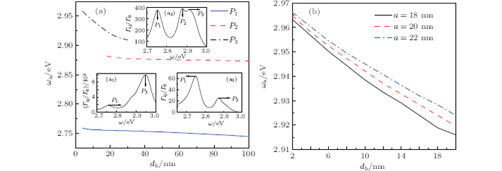
Figure 3(a) also shows another intriguing phenomenon where the peaks are red-shifted as db is increased. This phenomenon is similar to the case where the resonance peak of the extinction cross section of the ANP moves to a longer wavelength with the increase of its radius, where the dipole mode is modified by the higher-order modes under the long-wavelength approximation.[47] In this paper, we investigate the influence of the distance (db) on the frequency (ω a), which corresponds to the maximum of Γ ij. Here, da is fixed to be 2 nm, db is chosen to be from 4 nm to 100 nm and the other parameters are the same as those mentioned previously.
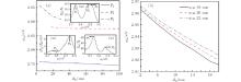
Figure 5(a) shows the influence of db on ω a. The solid line, dashed line, and dot– dashed line indicate the relevant frequencies at P1, P2, and P3, respectively, as shown in Fig. 3(a). It is clear that a monotonic decrease of ω a is present as the one QD (db) is moved away while the other one and the ANP are fixed. The P2 is inconspicuous for db < 16nm in Fig. 3(a). In the inset of Fig. 5 (a1), P2 does not show an observable feature. While db > 30 nm, P3 is difficult to observe, as indicated in the inset of Fig. 5 (a3). It is shown that P1, P2, and P3 can be seen clearly as db is between 16 nm and 30 nm in the inset of Fig. 5 (a2) . We can see that each of the curves for P1 and P2 is nearly a horizontal line. However, the curve for the position of P3 shifts dramatically compared with those of P1 and P2. To further explore the underlying physics behind this phenomenon, we examine the frequency shift at P3 by changing the radius of the ANP. The results are shown in Fig. 5(b). Monotonic relationships between ω a and db are found when the radii of the ANPs are 18, 20, and 22 nm. This shows that the radius has a slight influence on the monotonic relationship between ω a and db. In addition, it is interesting that as db is increased by 2 nm, ω a is reduced by about 5 meV, suggesting a tendency of the red-shift in wavelength.
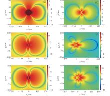
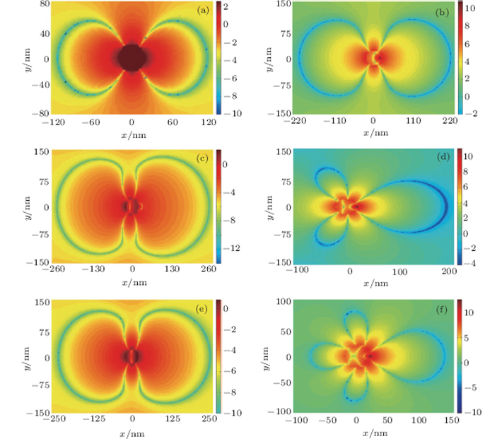
In Fig. 6, we investigate the property of the transfer rate by fixing one QD and changing the locations of the other QD in plane. The x and y represent the coordinates of QD (B). Here, ω 1, ω 2, and ω 3 are the frequencies at P1, P2, and P3, respectively, in Fig. 3(a). The values of ω are 2.75527 (ω 1), 2.87818 (ω 2), and 2.91964 (ω 3) eV, respectively, in Figs. 6(a) and 6(b), 6(c) and6(d), and 6(e) and 6(f). For the large value of da, the ANP dipole modes make the major contributions to Γ ij in the left panels (6(a), 6(c), and 6(e)) when QDs are far from the ANP, even though the transition frequencies are different. However, as shown in the right panels, the dominant modes are related to the transition frequency. This phenomenon shows that the higher-order modes come into effect and may make a major contribution to Γ ij if they match the transition frequency of the dipole as QDs are close to the ANP.
Fig. 5. Relationships between ω a and db with the radius of the ANP a = 18, 20, 22nm. Here ω a corresponds to the maximum of Γ ij/Γ 0, and da is fixed to 2 nm and db is changed.
Fig. 6. The ln | Γ ij/Γ 0| versus the position of atom B located at the xy plane. The da = 140nm ((a), (c), and (e)) and 2 nm ((b), (d), and (f)), respectively, for different values of ω . The other parameters are the same as those mentioned previously.
4. Conclusion
In this paper, the analytical Green function approach is used to study the interaction between two QDs. The RDDI is systematically calculated while the QDs are placed at different positions, where one QD is fixed at 2 nm from the surface of the ANP and the other QD is moved in plane. Our results show that RDDI becomes weak as the distance between two QDs increases gradually. In addition, the influence of higher-order modes of the ANP on the RDDI declines more quickly than that of dipole modes. Γ ij of the RDDI is nearly a constant over a broad frequency range where db is 22 nm and da is 2 nm, and the radius of ANP affects the above phenomenon slightly. The achievement of the wide frequency range can be useful in biology and medical sciences in the future. We find that the frequency corresponding to the maximum of Γ ij has a monotonically decreasing relationship with the distance between the ANP and the QDs changing from 4 nm to 140 nm. In addition, the radius of ANP has little effect on it. We show that the dipole modes of ANP contribute mainly to Γ ij when the distance is large. In contrast, when the distance is short, the higher-order modes of ANP become strong and dominate Γ ij if they consist of a transition frequency of the dipole. It should be noted that our method is universally applicable and it can be extended to other systems including multiple ANPs and multiple QDs of different angles. Furthermore, the results can provide a theoretical basis for designing molecular biological detectors and gaining an insight into the artificial characteristics of microstructures and micro-devices in depth.
ThonS M, RakherM T, KimH, GudatJ, IrvineW T M, PetroffP M and BouwmeesterD2009Appl. Phys. Lett. 94111115DOI:10.1063/1.3103885[Cited within:1][JCR: 3.794]
ProtsenkoI E, UskovA V, ZaimidorogaO A, SamoilovV N and O′ReillyE P2005Phys. Rev. A71063812DOI:10.1103/PhysRevA.71.063812[Cited within:1][JCR: 3.042]
33
ReinhardA, YoungeK C, LiebischT C, KnuffmanB, BermanP R and RaithelG2008Phys. Rev. Lett. 100233201DOI:10.1103/PhysRevLett.100.233201[Cited within:1][JCR: 7.943]
34
SaquetN, CournolA, BeugnonJ, RobertJ, PilletP and VanhaeckeN2010Phys. Rev. Lett. 104133003DOI:10.1103/PhysRevLett.104.133003[Cited within:1][JCR: 7.943]
35
Harland erM, LechnerR, BrownnuttM, BlattR and HaSel W2011Nature471200DOI:10.1038/nature09800[Cited within:2][JCR: 38.597]
... [1] The characteristics of QED have been studied in both theory and experiment, and a variety of QED devices have been proposed and developed by many researchers ...
This paper investigates the electromagnetic radiationcharacteristics of a metallic, large aspect ratio single walledcarbon nanotube antenna in the terahertz frequency region below 12.5THz. The key features of terahertz pulse have been revealed on thecarbon nanotube antenna in comparison with conventionalphotoconductive switching. The terahertz waveforms, radiation powerand their field distributions have been evaluated and are analysed.The Fourier transformed spectra over the whole frequency rangedemonstrate that the carbon nanotube antenna can be used asradiation source for broadband terahertz applications.
a Department of Electrical Science and Technology, HarbinUniversity of Science and Technology, Harbin 150080,China; b School of Electronics and InformationTechnology, HarbinInstitute of Technology, Harbin 150001, China; c School of Electronics and InformationTechnology, HarbinInstitute of Technology, Harbin 150001, China;Department of Electrical Science and Technology, HarbinUniversity of Science and Technology, Harbin 150080,China
This paper investigates the electromagnetic radiationcharacteristics of a metallic, large aspect ratio single walledcarbon nanotube antenna in the terahertz frequency region below 12.5THz. The key features of terahertz pulse have been revealed on thecarbon nanotube antenna in comparison with conventionalphotoconductive switching. The terahertz waveforms, radiation powerand their field distributions have been evaluated and are analysed.The Fourier transformed spectra over the whole frequency rangedemonstrate that the carbon nanotube antenna can be used asradiation source for broadband terahertz applications.
1
2013
3.042
0.0
1
2009
3.794
0.0
... 8] Some novel concepts, such as enhanced and inhibited spontaneous emission,[5,8] reversible spontaneous emission,[6] and the one-atom maser,[9] have been well known ...
1
2003
7.943
0.0
... 8] Some novel concepts, such as enhanced and inhibited spontaneous emission,[5,8] reversible spontaneous emission,[6] and the one-atom maser,[9] have been well known ...
1
2010
1.148
1.2429
3
1975
3.042
0.0
... 8] Some novel concepts, such as enhanced and inhibited spontaneous emission,[5,8] reversible spontaneous emission,[6] and the one-atom maser,[9] have been well known ...
... 8] Some novel concepts, such as enhanced and inhibited spontaneous emission,[5,8] reversible spontaneous emission,[6] and the one-atom maser,[9] have been well known ...
... A variety of electromagnetic environments have been used to control and modify these characteristics, such as a vacuum,[8,10] optical cavities,[11,12] photonic materials,[13] and metal surfaces,[14,15] and so on ...
1
1985
7.943
0.0
... 8] Some novel concepts, such as enhanced and inhibited spontaneous emission,[5,8] reversible spontaneous emission,[6] and the one-atom maser,[9] have been well known ...
A system consisting of two different atoms interacting with atwo-mode vacuum, where each atom is resonant only with one cavitymode, is considered. The effects of dipole--dipole ({dd})interaction between two atoms on the atom--atom entanglement andmode--mode entanglement are investigated. For a weak {dd} interaction, when the atoms are initially separable,the entanglement between them can be induced by the {dd}interaction, and the entanglement transfer between the atoms and themodes occurs efficiently; when the atoms are initially entangled,the entanglement transfer is almost not influenced by the {dd}interaction. However, for a strong {dd} interaction, it is difficultto transfer the entanglement from the atoms to the modes, but theatom--atom entanglement can be maintained when the atoms areinitially entangled.
College of Physical Science and Technology,Huazhong Normal University, Wuhan 430079, China
A system consisting of two different atoms interacting with atwo-mode vacuum, where each atom is resonant only with one cavitymode, is considered. The effects of dipole--dipole ({dd})interaction between two atoms on the atom--atom entanglement andmode--mode entanglement are investigated. For a weak {dd} interaction, when the atoms are initially separable,the entanglement between them can be induced by the {dd}interaction, and the entanglement transfer between the atoms and themodes occurs efficiently; when the atoms are initially entangled,the entanglement transfer is almost not influenced by the {dd}interaction. However, for a strong {dd} interaction, it is difficultto transfer the entanglement from the atoms to the modes, but theatom--atom entanglement can be maintained when the atoms areinitially entangled.
... A variety of electromagnetic environments have been used to control and modify these characteristics, such as a vacuum,[8,10] optical cavities,[11,12] photonic materials,[13] and metal surfaces,[14,15] and so on ...
1
2010
3.042
0.0
... A variety of electromagnetic environments have been used to control and modify these characteristics, such as a vacuum,[8,10] optical cavities,[11,12] photonic materials,[13] and metal surfaces,[14,15] and so on ...
Taking into account the energy and angular momentum transferred from a rotating black hole (BH) to the inner accretion disk by the magnetic connection (MC) process, we simulate the x-ray spectra from the disk-corona system with two different magnetic configurations using the Monte Carlo method. The results show that the MC process reduces the ratio of the power dissipated in the corona to the total and softens the spectrum. The influence of the MC process is stronger with a higher BH spin, a larger accretion rate, and a larger and more centralized magnetic flux threading the disk. The comparison of the model spectra with the observational data suggests that large-scale magnetic fields accumulating in the inner disk could be a candidate explanation for the hard-to-soft state evolutions in BH binaries.
1 School of Physics and Optoelectronic Engineering, Yangtze University, Jingzhou 434023 2 School of Physics, Huazhong University of Science and Technology, Wuhan 430074
... A variety of electromagnetic environments have been used to control and modify these characteristics, such as a vacuum,[8,10] optical cavities,[11,12] photonic materials,[13] and metal surfaces,[14,15] and so on ...
1
2011
3.546
0.0
... A variety of electromagnetic environments have been used to control and modify these characteristics, such as a vacuum,[8,10] optical cavities,[11,12] photonic materials,[13] and metal surfaces,[14,15] and so on ...
1
2011
3.385
0.0
... A variety of electromagnetic environments have been used to control and modify these characteristics, such as a vacuum,[8,10] optical cavities,[11,12] photonic materials,[13] and metal surfaces,[14,15] and so on ...
3
2011
0.0
0.0
... A variety of electromagnetic environments have been used to control and modify these characteristics, such as a vacuum,[8,10] optical cavities,[11,12] photonic materials,[13] and metal surfaces,[14,15] and so on ...
... Recent studies show that this kind of interaction has been applied to implement quantum entanglement preparation and quantum information processing,[15,22#cod#x2013 ...
... In previous theoretical studies, the transfer rate and the RDDI potential energy are obtained by numerical methods[15,24,35#cod#x2013 ...
A hybrid plasmonic waveguide consisting of a high-index dielectric core embedded inside a rectangular-shaped metallic trench is proposed and its guiding properties are investigated at the wavelength of 1550 nm. Numerical simulations based on the finite element method have demonstrated that the introduced dielectric core could greatly reduce the modal loss of the metal trench while maintaining strong confinement of light. The effects of dielectric core size, material of the cladding and the dielectric core on the modal properties have been systematically investigated. The proposed hybrid plasmonic structure can be realized employing fabrication techniques of the traditional metal trench waveguides and could be leveraged as important elements for highly-integrated photonic circuits. (C) 2013 Optical Society of America
... [16] Up to now, large numbers of SPP-based waveguiding structures have been investigated, including hybrid plasmonic waveguides,[17] metal stripes embedded in homogeneous dielectrics,[18] metallic nanowires,[19] metal slots,[20] etc ...
1
2010
3.546
0.0
... [16] Up to now, large numbers of SPP-based waveguiding structures have been investigated, including hybrid plasmonic waveguides,[17] metal stripes embedded in homogeneous dielectrics,[18] metallic nanowires,[19] metal slots,[20] etc ...
1
2000
0.0
0.0
... [16] Up to now, large numbers of SPP-based waveguiding structures have been investigated, including hybrid plasmonic waveguides,[17] metal stripes embedded in homogeneous dielectrics,[18] metallic nanowires,[19] metal slots,[20] etc ...
1
1997
3.385
0.0
... [16] Up to now, large numbers of SPP-based waveguiding structures have been investigated, including hybrid plasmonic waveguides,[17] metal stripes embedded in homogeneous dielectrics,[18] metallic nanowires,[19] metal slots,[20] etc ...
1
2005
3.794
0.0
... [16] Up to now, large numbers of SPP-based waveguiding structures have been investigated, including hybrid plasmonic waveguides,[17] metal stripes embedded in homogeneous dielectrics,[18] metallic nanowires,[19] metal slots,[20] etc ...
With the fast development of nanoscience and nanotechnology, research on the unique optical properties of metal nanostructures and related applications has rapidly grown into an important branch discipline of nano-optics, known as plasmonics, with abundant content and extensive applications in many fields such as biology, chemistry, renewable energy, and information technology. This article introduces some basic concepts of surface plasmons, including localized surface plasmons and propagating surface plasmon polaritons. An overview of various important applications in bio/chemo sensing, nanolasers, ultrafast optical switches, surface plasmon-based logic, and so forth is presented.
... [21] All these applications benefit from the extremely amplified and tightly confined local field, which leads to an ultra-small mode volume that significantly increases the light-matter interaction ...
1
2009
3.546
0.0
... Recent studies show that this kind of interaction has been applied to implement quantum entanglement preparation and quantum information processing,[15,22#cod#x2013 ...
1
2013
0.71
0.0
2
2005
7.943
0.0
... In previous theoretical studies, the transfer rate and the RDDI potential energy are obtained by numerical methods[15,24,35#cod#x2013 ...
... As explained by Hughes,[24] the peak of #cod#x0393 ...
1
2012
3.042
0.0
... [25] and [26], we can easily obtain(#cod#x0393 ...
This paper studies entanglement between two dipole--dipole coupledatoms interacting with a thermal field via a two-photon process. Itshows that the entanglement is dependent on the mean photon number ofthe thermal field and the dipole--dipole interaction. The resultsalso show that the atom--atom entanglement through the two-photonprocess is larger than that through the one-photon process and aremarkable amount of entanglement between the atoms still remains atcertain times even for a very highly noisy thermal field.
a Department of Physics, Hunan Normal University,Changsha 410081, China; b Department of Physics, Hunan Normal University,Changsha 410081, China;Department of Physics and Electronics, Zhuzhou Teacher'College, ZhuZhou 412007, China;Department of Physics, Hunan Industrial University,Zhuzhou 412000, China
This paper studies entanglement between two dipole--dipole coupledatoms interacting with a thermal field via a two-photon process. Itshows that the entanglement is dependent on the mean photon number ofthe thermal field and the dipole--dipole interaction. The resultsalso show that the atom--atom entanglement through the two-photonprocess is larger than that through the one-photon process and aremarkable amount of entanglement between the atoms still remains atcertain times even for a very highly noisy thermal field.
... [25] and [26], we can easily obtain(#cod#x0393 ...
... rster energy transfer,[30,31] dipole nanolasers,[32] etc ...
2
2002
3.042
0.0
... rster energy transfer,[30,31] dipole nanolasers,[32] etc ...
... [31] and [44], the transfer rate and the potential energy of the RDDI in the quantization scheme are ...
1
2005
3.042
0.0
... rster energy transfer,[30,31] dipole nanolasers,[32] etc ...
1
2008
7.943
0.0
... [33#cod#x2013 ...
1
2010
7.943
0.0
2
2011
38.597
0.0
... 35] All of these applications and phenomena mentioned above are related in essence to the transfer rate or RDDI potential energy ...
... In previous theoretical studies, the transfer rate and the RDDI potential energy are obtained by numerical methods[15,24,35#cod#x2013 ...
1
1998
3.042
0.0
1
2011
7.943
0.0
1
2008
3.042
0.0
... 38] or analytic methods ...
2
2001
3.042
0.0
... [39#cod#x2013 ...
... [39] It is obvious that the numeric values of #cod#x03B4 ...
1
1997
3.042
0.0
1
1995
3.042
0.0
1
2008
3.042
0.0
2
1997
3.042
0.0
... 43] For numerical methods, an independent program needs to sweep the parameters for the dipoles at different positions or with different polarizations, where a single run usually needs considerable computational resources for the finite element method (FEM) or the finite-difference time-domain (FDTD) method ...
... [43,46] The specific expressions are given in Appendix A ...
2
2006
0.0
0.0
... [44] ...
... [31] and [44], the transfer rate and the potential energy of the RDDI in the quantization scheme are ...
1
1971
0.0
0.0
... 1 is given as[45,46] ...
2
2012
0.0
0.0
... 1 is given as[45,46] ...
... [43,46] The specific expressions are given in Appendix A ...
1
1994
0.0
0.0
... [47] In this paper, we investigate the influence of the distance (db) on the frequency (#cod#x03C9 ...
1
1999
1.111
0.0
Position-dependent property of resonant dipole—dipole interaction mediated by localized surface plasmon of an Ag nanosphere*
[Xu Dan, Wang Xiao-Yun†, Huang Yong-Gang, Ouyang Shi-Liang, He Hai-Long, He Hao]


 , Huang Yong-Gang, Ouyang Shi-Liang, He Hai-Long, He Hao]