


Influence of the illumination coherency and illumination aperture on the ptychographic iterative microscopy*
[Liu Chenga), b)†  , Zhu Jian-Qiang
a) , John Rodenburgb) ]
, Zhu Jian-Qiang|
|


Corresponding author. E-mail: chengliu@siom.ac.cn
While ptychography is an algorithm based on coherent illumination, satisfactory reconstructions can still be generated in most experiments, even though the radiation sources that are used are not ideally coherent. The underlying physics of this phenomenon is that the diffraction patterns of partially coherent illumination can be treated as those of purely coherent illumination by altering the intensities of the diffracted beams relative to their real values. On the other hand, due to the inconsistency in the altering interference among all the diffraction beams, noise/distortion is always involved in the reconstructed images. Furthermore, for a weak object, the noise/distortion in the reconstruction can be mostly reduced by using a highly curved beam for illumination in the data recording and forcing the dark field diffraction to be zero in the reconstruction.
When an object is irradiated by coherent x-rays or electron beams, a diffraction pattern will be formed in the far field and this can be recorded digitally by a charge-coupled device (CCD) camera. From these recorded diffraction patterns the transmission function of the object can be reconstructed iteratively by using the coherent diffractive imaging (CDI) algorithm.[1– 5] In principle, CDI allows one to obtain a resolution that is ultimately limited only by the wavelength of the radiation used and not by the quality of the optics. Due to this outstanding advantage, CDI has become one of the most promising techniques for the applications of x-ray and electron imaging in nano-scale biology and material sciences. Impressive results have been reported, including the imaging of a freeze-dried yeast cell, [6] lead nano-crystals, [7] and gold nano-structures.[8] Furthermore, most of the principle limitations of the conventional CDI technique, including the limited field of view and the low convergence speed in the computation, can be eliminated by the recently developed ptychographical iterative engine (PIE) algorithm.[9– 11] This makes it possible to combine the traditional ptychography and diffractive imaging, which has succeeded in imaging with visible light, x-ray, and electrons.
In the above mentioned CDI techniques, illumination is always assumed to be perfectly coherent. However, the current synchrotron sources and electron beams will have only a much lesser coherence than the extremely high degree of spatial coherence of the free-electron laser. Consequently, the reconstruction of CDI techniques always suffer from partial coherence and they cannot reach the wavelength limited resolution. The role of coherence in coherent diffractive imaging has been discussed rather qualitatively[12] and a spatially coherent model decomposition method has been proposed to improve the reconstruction quality.[13] The advantages of curved illumination over planar illumination have also been analyzed.[14] However, the significance of coherence in CDI technique is still not fully understood and it is important for us to avert the problem of coherency to achieve a better resolution. In this paper, we investigate how partially coherent illumination is able to give a reasonably satisfactory reconstruction from its diffraction patterns and in what way the partial coherence influences the reconstruction. The origin of the noise/distortion related to the partial coherence is pointed out theoretically and verified numerically. Furthermore, a method to reduce the noise/distortion induced by partial coherence is suggested for imaging weakly scattering objects. To be specific, the diffraction patterns of partially coherent illumination can be regarded as a purely coherent pattern composed of diffracted beams with an altered intensity. Consequently, the images reconstructed by CDI algorithm are also weaker in intensity. Furthermore, for weakly scattering objects the diffraction patterns in the bright field and the dark field lead to two different reconstructions in terms of its diffraction capability and the extent of overlap between these two diffraction patterns would determine the amount of noise or distortion in the final reconstruction. By forcing the dark field diffraction patterns to be zero while processing the data, we are able to ensure that the remaining diffraction pattern gives rise to only one reconstruction. The quality of the resulting image can be remarkably improved. All of these results are verified by using computer simulations with the PIE algorithm, they are also valid for other coherent diffractive imaging techniques.
The optical setup for the PIE technique is schematically shown in Fig. 1, where the specimen with a transmission function of q(r) is fixed on a translation stage and is irradiated by a probe with distribution P(r). A CCD camera is used to receive the far-field intensity of the scatted electron beam. Since the CCD is in the far field of the object, the recorded diffraction pattern is proportional to the absolute square of the Fourier transformed scattered wave function. In this case, the recorded intensity can be written as I(k), i.e., I(k) ∝ | FFT[ψ e(r)]| 2. The momentum transfer k is the reciprocal coordinate with respect to the direct space coordinate r. The far-field intensities are recorded for different sample-to-probe positions shifted by a vector R. For a two-dimensional (2D) sample, the relationship between the exit wave and the illumination probe is given as ψ e(r, R) = q(r)P(r− R) and the phase retrieval starts with a random guess for the transmission function q0(r). The detailed iteration reconstruction procedure can be found in Ref. [9].
 | Fig. 1. Schematic diagram for principle of PIE. |
In the far field plane, the intensity of the diffraction patterns can be written as
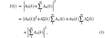
where the diffraction pattern is regarded as the interference between the zero-order beam A0(k) and the diffracted beams 
By defining I0(k)= | A0(k)| 2 and 

where φ (k) is the phase difference between A0(k) and
When the irradiation is not purely coherent, the contrast of the diffraction pattern will be reduced and equation (2) can be rewritten as

In Eq. (3), α (k) has a value ranging from 0 to 1.0, which indicates the contrast reduction due to the spatial coherency. Since the term Id(k) is the interference result of different orders of diffractions, its contrast is also changed by the spatial coherency, hence it is to be multiplied by another coefficient β (k) in Eq. (3). For weaker objects, the intensity of the diffracted beams Id(k) is quite less than that of the other terms in Eq. (3), and its multiplication with β (k) does not change the value I′ (k) much. Thus equation (3) can be approximated as

which can be rewritten as
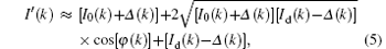
where

It is obvious that Δ always has a positive value. Equation (5) means that the diffraction patterns obtained with partially coherent illumination can be regarded as a diffraction pattern of pure coherency formed by a new zero-order beam I0(k)+ Δ (k) and new diffracted beam, Id(k)− Δ (k), which corresponds to a coherent diffraction pattern of a weaker specimen. It is also interesting to note that the reconstructions obtained from such diffraction patterns are of reduced intensity. This is the fundamental reason why a reasonably satisfactory image can be reconstructed from diffraction patterns of partial coherence. It will also be reasonable to find some very fine object structures in the reconstructed image in some practical CDI experiments, where the radiation source is not ideally coherent.
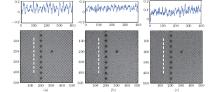
To verify the above analysis, a simulation on the silicon 〈 100〉 with some defects (missing atom column) is conducted with the multi-slice theory on the assumption that the electron energy is 200 kV, the thickness of the silicon is 18.12 Å , and the illumination angle is 12 mrad. In the simulations, the diffraction patterns of various spatial coherencies are calculated with multi-slice theory by wobbling the electron gun and summing up the diffraction intensity. The reconstructions are then performed by these computed diffractions inversely with the PIE technique. Figures 2(a)– 2(c) show the reconstructed phases when the effective electron gun widths are 0 Å , 2.2 Å , and 2.6 Å , respectively. In each figure the lower part is the reconstructed phase image and the upper part is the phase profile along the dash line. We find that the phase range in Fig. 2(a) is about 0.9 rads, and the phase range in Fig. 2(b) is about 0.6 rads, and the phase range in Fig. 2(c) is only 0.4 rads. The reconstructed phase contrast is reduced remarkably with the increase of the electron gun width in Fig. 2, this result matches with our above analysis very well.
 | Fig. 2. Reconstructed phase images for electron gun width of 0 Å (a), 2.2 Å (b), and 2.6 Å (c) when the numerical aperture is12 mrads. |
 | Fig. 3. Diffraction pattern with a numerical aperture of 10 mrad with spatial coherence. |
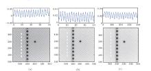
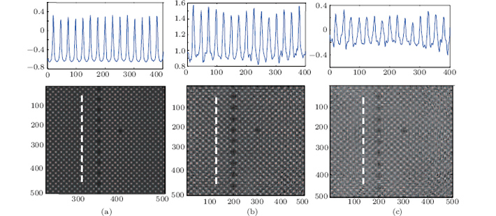
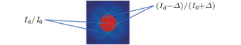
In Fig. 2, besides the reduction of the phase contrast there is also a remarkable distortion that increases with the electron gun width. To find out the origin of this distortion, a diffraction pattern of 〈 100〉 silicon is shown in Fig. 3, which corresponds to an electron gun width of 2.2 Å . If the intensity of the zero-order diffraction in Fig. 3 is assumed to be I0 and the intensity of the first order diffraction is assumed to Id, then according to the above analysis the effective zero-order intensity within the overlap is (I0+ Δ ) and the effective intensity of the diffraction is (Id− Δ ), and thus a reconstruction with the diffraction capability of (Id− Δ )/(I0+ Δ ) is determined by the overlapping data. However, for those diffractions outside the overlapping, because there is no interference there, the diffraction capability of the reconstruction will be Id/I0. Since these two diffraction strengths do not coincide with each other, the distortion will inevitably be generated in the reconstruction. Figure 4 shows the reconstructed phase images for electron gun widths of 3.2 Å (a), 3.6 Å (b), and 4.0 Å (c) when the numerical aperture is 30 mrad.
To produce more obvious noise, we repeat the simulations of Fig. 2 but with a larger gun width and show the reconstructed phase images in Fig. 4, where figures 4(a)– 4(c) correspond to gun widths of 3.2 Å , 3.6 Å , and 4.0 Å , respectively. We can find that when the gun width is 4.0 Å , the noise dominates the reconstruction and almost no crystal structure can be identified at the atomic resolution.
 | Fig. 4. Reconstructed phase images for electron gun widths of 3.2 Å (a), 3.6 Å (b), and 4.0 Å (c) when the numerical aperture is 30 mrad |
According to the above analysis, we know that the noise appears when there is a lack of coincidence between the diffraction strengths determined by different sets of diffractions, both with and without interference. While using a large numerical aperture for illumination, the bright un-diffracted disks will occupy most of the detector sensor, and due to its much stronger intensity than the diffracted beams, the interference between the un-diffracted beam and the diffracted beams will dominate over the interference among the diffracted beams. In other words, the interference between the diffracted beams can be neglected within the central un-diffracted disk. In the region outside the central bright disk, a large number of diffraction beams interfere with each other, and thus it is impossible to find a value for Δ to make all of these interferences coincide with each other. That is, the data outside the central bright disk cannot be treated as being purely coherent, which is the main origin of the noise or distortion in the reconstruction. Accordingly, by forcing the data outside the central disk to be zero in the reconstruction, the distortion induced by the spatial coherence can be reduced and, while a large numerical aperture is used for illumination, this will not lead to remarkable degradation in the resolution. Taking Fig. 5 for example, which shows a diffraction pattern calculated with a numerical aperture of 30 mrad and a gun width of 3.6 Å , most of the interferences take place inside the central bright field and thus it will provide a reconstruction weaker than expected. There will not be any noise in the reconstruction because we have forced the data outside the central disk to become zero.
 | Fig. 5. Diffraction pattern which is modified by forcing the data outside the central disk to be zero in the reconstruction. The numerical aperture for the illumination is 30 mrad. |
To verify this prediction, we repeat the reconstruction in Fig. 4 by forcing the data outside the central disk to be zero in the reconstruction process, the reconstructed phase images are shown in Fig. 6. By comparing it with the reconstructions in Fig. 4, we can find remarkable improvement in the image quality and almost no noise can be found in these reconstructions. This result matches very well with the above theoretical analyses. However, it can also be found that the resolution of the reconstruction becomes low in comparison with the reconstruction in Fig. 2(a). Such a degradation in spatial resolution is directly induced by abandoning the higher order diffractions outside the bright central disk, which correspond to the detailed structures of the sample. This is the disadvantage of the proposed method. Theoretically, the information lost while abandoning the higher order diffractions can be retrieved with a scheme similar to that of the super-resolution PIE, which will be investigated further in our research.
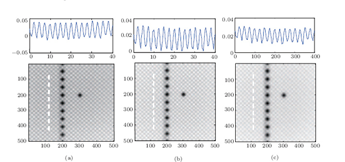 | Fig. 6. Reconstructed phase images for an electron gun width of 3.2 Å (a), 3.6 Å (b), and 4.0 Å (c) when the dark field data are forced to be zero. |
It is should be pointed out that in the above simulations the silicon crystal and the electron beam have been used as the sample and the illumination, respectively; however, the results obtained are also valid for microscopy with x-ray and visible light because the imaging principle is exactly the same for all kinds of radiations, irrespective of their wavelength.[15, 16] On the other hand, the theoretical analysis and the results obtained are only valid for a weakly scattering object because the strength of the zero-order diffraction should be strong enough, its interference with the diffracted beams can then dominate the structure of the diffraction patterns. For a strongly scattering object, the strength of the high order diffraction beams can be much stronger and they cannot be neglected in the reconstruction.
In conclusion, the physics behind the influence of spatial coherence in ptychography is investigated numerically. It is found that the diffraction patterns of partially coherent illumination can be roughly regarded as those of purely coherent illumination composed of diffracted beams with alternate intensities. The reconstruction from this kind of diffraction is much weaker in intensity. The origin of noise in the reconstruction involving illumination with partial coherence is investigated and is found to be due to the fact that two sets of diffraction patterns are formed: one is within the central disk and the other is outside the central disk. This can be avoided by forcing the outer dark-field data to be zero in the reconstruction processing. All of our conclusions are verified by simulations with the PIE algorithm and they should also be valid for other CDI techniques.
| 1 |
|
| 2 |
|
| 3 |
|
| 4 |
|
| 5 |
|
| 6 |
|
| 7 |
|
| 8 |
|
| 9 |
|
| 10 |
|
| 11 |
|
| 12 |
|
| 13 |
|
| 14 |
|
| 15 |
|
| 16 |
|