


Dynamics of magnetic skyrmions*
Cite this Article
Liu Ye-Hua, Li You-Quan. Dynamics of magnetic skyrmions* . Chinese Physics B, 2014, 24(1): 017506 
Permissions
Dynamics of magnetic skyrmions*
Corresponding author. E-mail: yqli@zju.edu.cn
Project supported by the National Natural Science Foundation of China (Grant Nos. 11074216 and 11274272) and the Fundamental Research Funds for the Central Universities of China.
Abstract
We review the recent progress on the magnetic skyrmions in chiral magnetic materials. The magnetic skyrmion is a topological spin configuration with localized spatial extent, which could be thought of as an emergent rigid particle, owing to its particular topological and chiral properties. Static skyrmionic configurations have been found in various materials with different transport and thermodynamic properties. The magnetic skyrmions respond to externally applied fields in a very unique way, and their coupling to other quasiparticles in solid-state systems gives rise to the emergent electrodynamics. Being not only theoretically important, the magnetic skyrmion is also very promising to be the information carrier in next generation spintronic devices.
Keyword:
75.70.Kw; 75.78.–n; 75.30.Ds; skyrmion; chiral magnet; manipulation
1. Introduction
Spatially localized, topologically protected objects always attract enormous attention because of both the theory and application interests. The study of such kind of objects, like the magnetic domain wall and the vortex in superconductors, has led to many advances in physics, which greatly deepened our understanding of nature and significantly influenced our daily life. In the last few years, the discovery of the topological object, called the skyrmion, in chiral magnetic systems has triggered a new wave of extensive studies of topological objects in the context of magnetism.
The skyrmion was originally proposed by the British physicist Tony Skyrme, in the context of particle physics, with the aim to explain the stability of particles by their topological properties.[1] The skyrmion that we will introduce in this review is the manifestation of this idea in magnetism. As currently understood, chiral magnets are very unique for the formation of magnetic skyrmions. Because of the lack of the inversion symmetry in the crystal structure, a definite chirality of the magnetic orders is selected, which is favored in the viewpoint of free energy.[2– 4] At the same time, the skyrmion is a chiral object, so under certain conditions, there could be a massive amount of skyrmions nucleated in a chiral magnetic system. Once nucleated, the skyrmion would have both the free energy protection and the topological protection. This double protection gives the skyrmion the nature of rigidity.
To detect the existence of the skyrmions, people often adopt two complementary approaches, either in the momentum space via neutron scattering, [3] or in the real space by the Lorentz transmission electron microscopy.[5] The material systems that host the skyrmions are also very rich, there are three-dimensional bulk systems[3, 6] and two-dimensional thin film systems; [5, 7, 8] conductors[3, 5] and insulators; [6] conventional magnets and multiferroics.[6, 9, 10] More and more chiral magnets are being discovered in recent years.
The skyrmions also have very rich dynamic properties when they respond to various external perturbations. In conducting materials, an applied electric current could push the skyrmion to move, or even rotate when an additional temperature gradient is present; [11] in a system with localized pinning centers, the skyrmion feels the pinning force and performs a circular motion; [12] in multiferroic chiral magnets, the skyrmion responds to the electric field gradient and performs Hall motion.[13] The motion of skyrmions as point particles is well understood now.[14] As a rigid body, the skyrmion responds to the applied forces in a non-Newtonian way. For steady enough motion during which no internal modes are excited, there is no acceleration process for skyrmion's lack of inertial mass, and the skyrmion tends to move perpendicularly to the applied forces. Concerning the dynamics of the internal structure of the skyrmion, a collection of internal modes could be excited by ac electromagnetic fields of different symmetries.[13, 15, 16] The dynamical properties of the skyrmions are very important for potential applications.
In a solid-state system, the skyrmion may couple to other quasiparticles in a very special way. It was discovered that the skyrmion could contribute an emergent electromagnetic field to quasiparticles with spin.[17, 18] Static skyrmionic order contributes a magnetic field, and dynamical skyrmionic order also contributes an electric field. For the electrons, there are the so-called topological Hall effect[17– 20] and the emergent Faraday's law; [18]for the magnons, there are the thermal Hall effect[21] and the skew scattering phenomenon of magnons off skyrmions.[22– 24] These kind of phenomena are collectively called the emergent electrodynamics.
The massive amount of progress in this field makes the skyrmion a very promising candidate for information carriers in next generation information devices. There had been a major effort to realize memory devices by the so-called magnetic bubbles[25] in the last century. The magnetic bubble has nearly the same topological property as the skyrmion, however, the mechanism for the stabilization of the magnetic bubbles is very different from that of the skyrmions. It turns out that the magnetic bubbles have several disadvantages comparing to other approaches to memory devices at that time. The project of magnetic bubble was finally abandoned, however, we could think of the skyrmion as an alternative to replace the magnetic bubble as a crucial component of novel memory devices.
2. Description of the skyrmion
Let 
 |
is an integer if the continuous mapping 
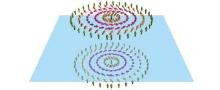
The skyrmion is not only topological, it is also chiral, which means the skyrmion has a definite “ sense of rotation” . Chirality is a mathematical property of geometrical figures. The inventor of this concept, Lord Kelvin, had the following statement, “ I call any geometrical figure, or group of points, chiral, and say that it has chirality if its image in a plane mirror, ideally realized, cannot be brought to coincide with itself” . Mathematically, the mirroring operation is defined by x → x, y → y, and z → − z if we assume the mirror plane to be the z = 0 plane in the Cartesian coordinate system. After the mirroring, we can also perform a rotation of π about the z axis, which does not change the chiral properties. These two combined operations define the inversion operation about the axis origin, r → − r. In magnetism, we are interested in spin configurations. As we know, the spin S is an axial vector like the angular momentum. The axial vector behaves differently under mirroring, which is Sx → − Sx, Sy → − Sy, and Sz → Sz (again assuming the mirror plane z = 0). The inversion follows to be S → S, i.e., axial vector is unchanged under inversion. With the above definitions, the mirror image of a spin configuration is defined by
 |
and the associated inversion is defined by S(r) → S(− r). Now we can see that the skyrmion is a chiral object after comparing the skyrmion with its mirror image in Fig. 1.
In chiral magnets, the crystal structure selects the chirality, so a skyrmion is protected by its chirality as well as its topology. The skyrmion in chiral magnets has this double protection so it is very rigid, behaving like an emergent particle.
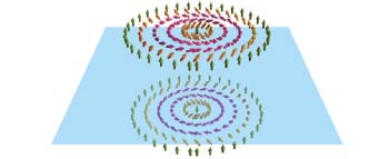 | Fig. 1. The skyrmion (top) and its mirror image (bottom), which could not be brought to coincide with each other by translation and rotation. Thus the skyrmion is a chiral object. |
3. Material and model
3.1. First observation in MnSi
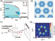
The first confirmation of the existence of magnetic skyrmions was published in 2009, by the German group of Pfleiderer et al.[3] Utilizing the small-angle neutron scattering (SANS), they investigated the phase diagram of the itinerant chiral magnet MnSi in the parameter space of temperature and magnetic field. They found that in the whole region below the transition temperature and the polarizing magnetic field, the system shows chiral magnetic phases. The appeared phases include the helical phase in small field, the conical phase in low temperature and intermediate field, and the skyrmion crystal phase (which is also called the A-phase) in the vicinity of the transition temperature at intermediate field (Fig. 2). The skyrmion crystal manifests in SANS as a six-fold pattern of Bragg peaks perpendicular to the external magnetic field. If a Fourier transform is performed to this momentum-space signal, a close-packed skyrmion lattice is obtained. This pattern of the order parameter is very similar to the Abrikosov lattice observed in type-II superconductors.
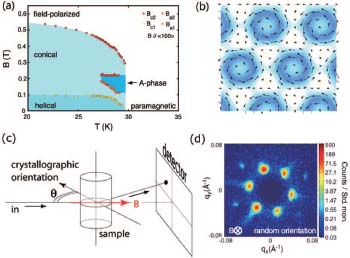 | Fig. 2. (a) The phase diagram of MnSi in the temperature– magnetic field plane. (b) Schematic of the close-packed skyrmion crystal. (c) Geometry of the neutron scattering experiment. (d) The six-fold Bragg peak pattern for the skyrmion crystal.[3] |
As a matter of fact, back in 2006, Rö ß ler et al. predicted the existence of skyrmion crystal in MnSi.[2] The theoretical understanding is based on the lack of inversion symmetry in this material, so that phenomenologically, an odd order term of spatial gradient ∇ is allowed.[29– 31] According to the macroscopic isotropy of the system, this term is like
 |
where D represents the strength of the inversion asymmetric effects, and M(r) is the magnetic order parameter. This term is manifestly isotropic, but lacks the inversion symmetry due to the odd order of ∇ . If we perform an inversion to the order parameter, then we will have a sign change of the free energy, which reads
 |
It means that only chiral spin orders can contribute to this free energy term with inversion asymmetry.
The aforementioned term also has a microscopic origin, which is the Dzyaloshinskii– Moriya (DM) interaction. Historically, Dzyaloshinskii proposed the interaction term in a phenomenological way; [32] then Moriya derived the term microscopically by generalizing Anderson's superexchange theory to the case with the spin– orbit interaction; [33] and more than thirty years later, Shekhtman et al. found a hidden symmetry in this term and simplified the derivation greatly.[34] The DM interaction is a bond energy in the form of
 |
where Dij (often called the D-vector) is a vector coupling constant defined on the bond between sites i and j, and it is nonzero only if the center of the bond is not a point of inversion symmetry in the crystal. The antisymmetry of the cross product is consistent to the lack of inversion symmetry in the magnetic system.
Besides the DM interaction, there are also the more conventional Heisenberg interaction and Zeeman interaction in this material, thus the minimal model of MnSi is
 |
The dimension of 𝓗 is energy density, and each term in the above equation has the same dimension. The J term contains one more gradient than the D term, so we can construct a length scale by coupling constants J and D to be J/D. This length scale turns out to be the typical wavelength of spin modulations in the chiral magnetic phases, for example, the helical wavelength in helical and conical phases, and the inter-skyrmion distance in the skyrmion crystal phase.
The competition of various chiral magnetic orders in low temperature could be addressed by the method of variation. The trial function of helical and conical orders is
 |
where β is the cone angle; when β = π /2, it becomes the helical order. The variational parameters are β and k, where k ∝ D/J is induced by the DM interaction, a deviation from β = π /2 is induced by the Zeeman effect.
On the other hand, the trial function of an isolated skyrmion is[30, 31]
 |
Here we have adopted the cylindrical coordinate system, with local frame vectors 
To explain why the skyrmion crystal only appears in the vicinity of Tc, Rosch et al. calculated the effect of thermal fluctuation to the Gaussian level.[3] Theoretically, all thermal fluctuations are included in the partition function Z= ∫ 𝓓 M(r), exp(− F[M(r)]), where F is the Ginzburg– Landau energy functional (which is closely related to Eq. (6)). In the mean-field level, as in the variational analysis, the stationary state M0 satisfies δ F/M|M0 = 0; to include the Gaussian fluctuation, one expands F around the stationary state to the second order and then performs the path integral, [35, 36] which leads to the effective free energy
 |
After substituting M0 by each of the variational states, one can compare their free energy in the vicinity of Tc. In the mean-field level, the skyrmion crystal has larger average energy density than the conical state, but its thermal fluctuation contribution to the free energy is smaller, so it is more favorable near Tc.
 | Fig. 3. Schematic for the tilted Heisenberg model. In the process of exchange interaction, neighboring spins undergo a relative rotation, which is defined on the bond of the neighbors. For the same spin (b2), the rotation matrix is different when it interacts with different neighbors (a1 and a2).[37] |
The Heisenberg and DM interactions are sufficient to describe chiral magnets with the skyrmion order. However, as pointed out by Li et al., there is a more elegant way to address the combined effects of these two interactions via non-abelian gauge fields.[37] It turns out that the spin orders with nontrivial spatial modulations could be the ground state of the following tilted Heisenberg model
 |
where J is the strength of the magnetic exchange interaction, 
Every SU(2) matrix has an image in SO(3) via a group homomorphism. Let the image of Ujj' be a 3 × 3 orthogonal matrix Ojj', then it is possible to rewrite 
 |
where 

The tilted model is most transparent after a continuum limit operation j → r, Sj → M(r), and ∑ j → a− d ∫
 |
where Dν M = ∂ ν M + Aν × M is the so-called covariant derivative as in the gauge field theory.
With the above Hamiltonian, it is straightforward to derive the equation of motion of the spin field M(r, t)
 |
which is a generalization of the Landau– Lifshitz equation (LLE) in the case with the tilt effect. If the gauge fields are identically zero, then Dν = ∂ ν and the equation becomes the conventional LLE. The equation of motion with gauge fields is called the gauge Landau– Lifshitz equation (GLLE). There is an intrinsic relationship between the gauge fields and the D-vector in the DM theory, namely, Djj' = aJAν (j).
The Hamiltonian and the GLLE are all in gauge covariant form, which makes it very easy to perform gauge transformations to an already known solution, so as to generate new solutions. In this way, the authors unified several important spin orders and their spin waves.
Owing to the geometric meaning of the covariant derivatives, [39] the tilted models are classified into two classes, the pure gauge class with [Dμ , Dν ] = 0 and the frustrated class with [Dμ , Dν ] ≠ 0. For the pure gauge class, there always exists a gauge transformation from the tilted model to the zero gauge model (the model with zero gauge is just the conventional Heisenberg model with the ferromagnetic order as the ground state). However, for the frustrated class, it is not easy to find the ground state because there is a frustration induced by the gauge fields, i.e., it is not possible to optimize the bond energy in every direction simultaneously. The skyrmion lattice solution belongs to the latter class with
 |
Substituting the gauge fields (Eq. 14) into the Hamiltonian (Eq. 12), we obtain (setting a = 1)
 |
which is the same as Eq. (6).
It is worth noticing that the mathematical form of non-abelian gauge fields is very suitable to describe condensed matter systems with spin– orbit interaction (microscopically, the DM interaction originates from the spin– orbit interaction). It has also been used in the study of the spin Hall effect[40] and multi-component cold atom systems.[41– 43] The tilted Heisenberg model is recently related to multiferroics with octahedral distortion.[44]
3.2. Two-dimensional skyrmion crystal
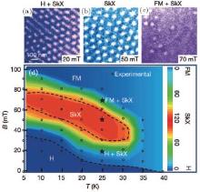
In 2010, the Japanese group, Tokura et al. observed the skyrmion crystal in real space[5] by the Lorentz transmission electron microscopy.[45– 48] The material system is thin film Fe0.5Co0.5Si, which is effectively a two-dimensional system because the film thickness is smaller than the typical modulation wavelength of spin orientation in this material. In comparison to the phase diagram of MnSi, the conical phase is absent in the thin film material. This is because, for the conical state, the modulation wave vector is parallel to the external field; but at the same time, the external field is put perpendicular to the film, so the conical state can not exist. In the absence of the conical state as a competitor, the skyrmion crystal dominates all the temperature region in the intermediate field, which makes the skyrmion more stable in the two-dimensional system (Fig. 4). Note that Han et al. adopted the two-dimensional version of Eq. (6) and successfully reproduced qualitatively the phase diagram by a Monte Carlo simulation.[4, 5] The Monte Carlo simulation of the three-dimensional version of Eq. (6) was published very recently.[49, 50] There is also a theoretical study of the quasi-two-dimensional properties of the thin film systems, [51] i.e., the modulation of spin structure along the film thickness direction.
 | Fig. 4. Spin orders detected by the Lorentz transmission electron microscopy for thin film Fe0.5Co0.5Si: (a) helical and skyrmion coexistence order, (b) the skyrmion crystal order, (c) ferromagnetic and skyrmion coexistence order. (d) The phase diagram of thin film Fe0.5Co0.5Si. Comparing to the phase diagram of MnSi, the conical order is suppressed in the two-dimensional systems.[5] |
The observed major difference between the phase diagrams of two- and three-dimensional systems inspired Yu et al. to establish a continuous link between the two limits.[7] They performed a series of experiments on the FeGe system and obtained the film thickness dependence of the magnetic phase diagram (Fig. 5). Just as expected, the larger the film thickness, the more resemblance the phase diagram to that of the MnSi system, i.e., the skyrmion crystal phase is pushed to the small region in the vicinity of Tc in the thicker samples.
In addition to the stability of the skyrmions, the two-dimensional system has another advantage that it is possible to realize a very large DM interaction. For example, if we grow one layer of the sample on a substrate, then below the sample it is the substrate and above the sample it is vacuum, so there is a very significant mirror asymmetry. In 2011, the German group, Blü gel et al. observed a skyrmion crystal in a single layer of iron on top of the Ir(111) substrate.[8] The mirror asymmetry is so large that the spin orientation changes very fast and each skyrmion has only atomic size, which means that each skyrmion consists of only several magnetic atoms. If we could make the skyrmions to be information carriers in devices, then the atomic size of each skyrmion will make the information density very large.
 | Fig. 5. Film thickness dependence of the magnetic phase diagram of FeGe. The thicker the film, the more resemblance the phase diagram to that of MnSi. The skyrmion crystal order is pushed to higher temperature regions in thicker films.[7] |
In the above, we have introduced the skyrmions in two- and three-dimensional systems. It should be noted that these skyrmions are intrinsically two-dimensional objects (the mathematical definition only involves an integral over two dimensions). In recent years, some authors begin the study of truly three-dimensional topological structures.[52– 54] And even in two dimensions, there are still other spin structures that have more complicated forms of spin modulation.[55– 57] Besides the magnetic systems with infinite spatial extent, the skyrmions could also exist in confined geometries like nanodisks[58, 59] and nanowires.[60– 62]
3.3. Multiferroic skyrmion crystal
Multiferroic material is a class of materials with more than one of the “ ferro-” orders, which are magnetization, polarization, and strain.[63– 67] Multiferroic materials with coupled magnetization and polarization are called magnetoelectric multiferroics, and in these systems there exists a new kind of elementary excitation, called the electromagnon, which is a coupled dynamic mode of electric and magnetic degrees of freedom.[68– 70]
In 2012, Seki et al. discovered the first magnetoelectric multiferroic material Cu2OSeO3[6, 9, 10] with both electric polarization and skyrmion crystal magnetic order. The unit cell of this material contains 16 copper atoms, each being surrounded by several oxygen atoms, forming a ligand structure. The valence electron of the oxygen is the p electron, which has different orbital symmetry from the d electron of the copper atom. The mixing, or hybridization, of these two orbital states leads to a redistribution of the electron cloud, thus a microscopic polarization on the copper– oxygen bond appears. It turns out that the microscopic polarization is determined by the angle between the direction of the magnetic moment on the copper atom and that of the copper– oxygen bond, so the magnetic order could induce an electric order in this material. This is called the pd-hybridization mechanism of multiferroics.[71, 72] To be complete, there are other microscopic mechanisms for multiferroics, such as the spin-current mechanism[73, 74] and the exchange striction mechanism.[66]
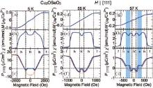
To prove the multiferroicity of this material, Seki et al. measured the magnetic field dependence of the electric polarization, the macroscopic magnetization, and the magnetic susceptibility. These three quantities always show significant changes at the same magnetic field (Fig. 6), which confirms that the electric and magnetic degrees of freedom in this system are strongly coupled.
The existence of multiferroic skyrmion crystal makes it possible to design magnetoelectric spintronic devices, in which the topological magnetic structure is manipulated by means of the electric field. The electric field in insulating materials causes negligible Joule heating, compared with the electric current in conducting materials. The Cu2OSeO3 system has thus attracted much attention since this discovery.[75– 80]
 | Fig. 6. The magnetic field dependence of magnetization M, magnetic susceptibility χ ', and electric polarization P, in different temperatures, for the material system Cu2OSeO3. The three curves always show significant changes at the same magnetic field, showing the strong coupling between the electric and the magnetic degrees of freedom. There is nonzero electric polarization in the skyrmion crystal phase (denoted by s in (i)), which makes it possible to manipulate the skyrmion via electric fields.[6] |
Liu et al. first addressed the potential application of the multiferroic chiral magnets from a theoretical point of view.[13] By observing the experimental data and the crystal symmetry of Cu2OSeO3, a macroscopic relation between the magnetic order and the electric polarization is proposed as follows:
 |
where λ , with the dimension of electric polarization, is the magnetoelectric coupling constant. This relation obviously satisfies the cubic symmetry of the crystal system. The quadratic and on-site nature of the relation are inherited from the more microscopic pd-hybridization formula. Here i denotes the site number of one unit cell of the crystal structure, which contains 80 copper– oxygen bonds. Equation (16) could be viewed as an average effect of the microscopic polarization, on each copper– oxygen bond, within one unit cell. Similar form of the magnetoelectric coupling also exists in multiferroic Ba2CoGe2O7.[81, 82]
Equipped with the magnetoelectric coupling formula, the coupling to the externally applied electric field could be written as
 |
Thus the full model Hamiltonian reads
 |
where HHDM contains the Heisenberg and the DM interactions, HZ the Zeeman coupling, and HME the magnetoelectric coupling. With this model, the authors computed the thermodynamic magnetoelectric susceptibility, which shows very good agreement with the experiment.[83, 84] There is also a theoretical study on the manipulation of domain walls via electric field in multiferroic materials.[85]
4. The motion of skyrmions
The thermodynamic state of the skyrmion crystal is confirmed by various experiments, as introduced in the previous section. To make use of the skyrmions, we need to understand the motion of them in response to various external fields. Each skyrmion actually contains a large number of microscopic degrees of freedom, because it is made by a large number of spins. Thus the skyrmion has many modes of motion around its equilibrium state. From the viewpoint of theory, we can assert the existence of gapless modes, which correspond to the Goldstone modes of broken translational symmetry by the skyrmion crystal. Such modes resemble to the acoustic phonon modes in a crystal lattice. On the other hand, some of the low-lying modes are gapped, which resemble to the optical phonon modes in a lattice with a complex unit cell.
4.1. The electric-current driven skyrmion motion
We first introduce the collective motion of the skyrmion crystal in an applied current. Such kind of motion is familiar in the magnetic domain wall physics, in which a well-known mechanism called the spin-transfer-torque (STT) could push the domain wall to move parallel to the applied electric current.[86– 90] The STT mechanism could be understood in the following way, the electron in the applied current has spin 1/2, which couples to the magnetization in the material by the Hund's coupling, such that the spin of the electron is always parallel to the local magnetization in its trajectory. If the magnetization is non-collinear (as in a domain wall), then a torque is exerted to the electron by the magnetization, which further results a counter torque from the current to the magnetization. It is this counter torque that pushes the domain wall to move.
The manifestation of the STT in the skyrmion physics is discovered by Jonietz et al.[11, 91] They applied an electric current to MnSi and studied the change of the neutron Bragg peaks. Under the current, the six-fold peaks of the skyrmion crystal have a broadening with no change of the position; but by further applying a temperature gradient, the peaks undergo a collective rotation around their center; reversing the current leads to a reversed rotation. Jonietz et al. explained this phenomenon by generalizing the idea of the STT to the skyrmion physics, which turns out to lead to an effective magnetic field applied to the applied current.[17, 92, 93]
Let us first study a simple case, with three magnetic moments 


 |
where
 |
is the solid angle spanned by the three magnetic moments. In the calculation, we have used the identity (a · σ )(b · σ ) = (a · b) + i(a × b)· σ for arbitrary a and b.
We can then proceed to the continuous case, let the three magnetic moments locate at 
 |
in the last line, we have interpreted this Berry curvature as an emergent magnetic field similar to the Aharonov– Bohm effect. It is very important to note that the emergent magnetic field is proportional to the topological charge density of the skyrmion. For a complete skyrmion, the total topological charge is 4π , and typically a skyrmion has a length scale of several tens of nanometers. By using these two numbers, it could be estimated that each skyrmion contributes to the emergent magnetic field in the order of 2.5 T, which is very significant.
Because of the emergent magnetic field, the applied current is subjected to a substantial emergent Lorentz force, which leads to a counter force to the skyrmion lattice. Beside the emergent Lorentz force, the skyrmion lattice also feels the drag force from the applied current.
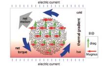
The experiment could be explained as follows. The magnetization is larger in the lower temperature region because of the smaller thermal fluctuation, and the Hund's coupling is stronger with larger magnetization. Thus the force from the applied current is larger in the region with lower temperature. As a result, the skyrmion crystal feels a net torque, which makes it to rotate (see Fig. 7).
 | Fig. 7. Schematic of the collective rotation of the skyrmion crystal. In a temperature gradient, the magnetization is larger in low temperature regions, thus the coupling to external electric current via the spin-transfer-torque is larger at theses places. The skyrmion crystal feels an overall torque, which makes it to rotate.[11] |
On the other hand, Zang et al. generalized the Berry phase theory for the skyrmions[94] and derived the ω ∝ k2 dispersion relation of the skyrmionic phonon mode.[95] Tchoe and Han investigated the effect of a circular electric current and found that it could generate skyrmions locally, which is the first theoretical proposal to generate skyrmions dynamically in chiral magnets.[96] It is more recently found by Zhou and Ezawa that there is a reversible conversion process between a skyrmion and a domain-wall pair, which also makes it possible to nucleate skyrmions dynamically.[97]
The interaction between the skyrmions and the electric current is very important for applications, thus it has attracted much attention.[98– 100]
4.2. The skyrmion as a non-Newtonian particle
The experiments of Jonietz et al. inspired people to ask the question: if a skyrmion feels an applied force, how does it move? We know that for a Newtonian particle, it will accelerate in the direction of the force, with the acceleration equal to the ratio between the force and the mass (Newton’ s second law). If we treat an isolated skyrmion as a particle, we could solve the motion of its center-of-mass by the Landau– Lifshitz equation (LLE). This kind of theory was developed by Thiele in the 1970s.[101]
The skyrmion is a collection of spins, and the spin moves according to the Landau– Lifshitz equation
 |
We have five terms on the left side, they are the kinetic term, the precession term, the damping term, the adiabatic STT term, and the non-adiabatic STT term, respectively.[86] In this equation, 
 |
α (called the Gilbert damping) is the dimensionless damping parameter, j is the applied electric current, and β is the relative strength of the non-adiabatic STT to the adiabatic STT.
We assume that the skyrmion moves without changing its shape, then
 |
where 
 |
where V= d R/dt is the skyrmion’ s velocity.
Thiele invented a trick to change the LLE, which is a torque equation, to a force density equation by defining the following force density:
 |
where X is each of the five terms in the LLE. For example, the kinetic term is changed to (we adopt the Einstein's convention, with repeated indices meaning summation)
 |
The force density, when integrated over the whole space, becomes a force
 |
where
 |
is the topological charge of the skyrmion.
The F1 is Lorentz force-like, which is perpendicular to the velocity of the skyrmion. The “ charge” (as in the conventional Lorentz force for charged particles) of the skyrmion is just its topological charge.
Similar calculations give the forces corresponding to the other terms in the LLE, which are
 |
where
 |
is the form factor of the skyrmion, which is a diagonal tensor for the cylindrical-symmetric skyrmion, i.e., Dxx = Dyy > 0, Dxy = Dyx = 0.
The force F2, which originates from the precession term in the LLE, is a conservative force. It is opposite to the partial derivative of the total energy to the center-of-mass coordinate of the skyrmion R (as in the definition of conservative force in classical mechanics). The force F3 is a damping force, which is opposite and proportional to the velocity. Forces F4 and F5 are exerted by the applied current. With all these forces, we can write down the equation governing the motion of the center-of-mass of the skyrmion, which is
 |
When the magnetic system is non-uniform, the skyrmion has different magnetic energies when it is put in different places in the system, which will lead to the conservative force − ∂ H / ∂ R. In this case, we have F2μ = Nε μ ν Vν and the skyrmion moves perpendicularly to the conservative force F2 (without the changing of the energy); with damping, we will have F2μ = Nε μ ν Vν + α Dμ ν Vν and the skyrmion has a tendency to move parallel to the conservative force to lower its energy (which is the precise meaning of damping). This kind of motion is crucial to the pinning and depinning processes of the skyrmions.
When there is no conservative force (or the system is translational invariant), no damping, and no non-adiabatic STT, we have the solution V = j and the adiabatic STT will push the skyrmion to move parallel to the current.
When the non-adiabatic STT has the same strength as the Gilbert damping, α = β , there is a cancellation between the terms α Vν and β jν , and in this case we still have the solution V = j.
The above simple phenomena predicted by the Thiele equation are verified by several authors using extensive numerical simulations of the LLE. Several remarks are in order. 1) The equation of motion is first order in time derivative, so the skyrmion has no process of acceleration, no inertia. Instant force results in instant motion. 2) The effective charge in the Lorentz-like force is the skyrmion’ s topological charge, so topologically trivial objects have no Lorentz force attached to them. 3) The applied current pushes the skyrmion to move parallel to it, which makes it possible to manipulate the skyrmion by electric means.
In the literature, the skyrmion, as a point particle, is called non-Newtonian because of the features mentioned in the above remarks. It should be noted that when the skyrmion's rigid motion is coupled to its internal motion, an effective mass could be generated by this coupling.[102] For most cases, a massless particle picture is enough to understand the physics.
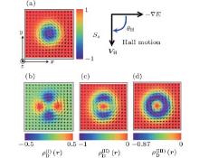
One novel application of the non-Newtonian motion is the response of a multiferroic skyrmion to an applied electric field gradient. As introduced in Section III C, in the multiferroic chiral magnet Cu2OSeO3, each skyrmion carries an electric dipole (Fig. 8). Thus in an electric field gradient, the skyrmion shall feel an electric force, and starts to move. As predicted by the Thiele theory, the direction of motion should be perpendicular to the electric field gradient in the case of no Gilbert damping. Liu et al. carried out extensive numerical simulations of the LLE to trace the trajectory of the skyrmion, the resultant direction of motion and the velocity show perfect agreement with those predicted by the simple Thiele theory.[13]
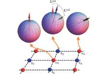
 | Fig. 8. (a) An isolated skyrmion. (b)– (d) The electric polarization distribution of the skyrmion, in three crystal orientations: (b) B∥ [001], E∥ [001]; (c) B∥ [110], E∥ [001]; (d) B∥ [111], E∥ [111]. In panels (c) and (d), the skyrmion has a net electric polarization, thus it could couple to the external electric field gradient, and move perpendicularly to the field gradient because of the non-Newtonian nature.[13] |
4.3. The pinning of skyrmions
Another important aspect of the skyrmion dynamics is the pinning of skyrmions. Pinning is a very common phenomenon for localized objects in a non-uniform medium. A more familiar example is the pinning of vortices in type-II superconductors.[103] A pinned object tends to stay in specific positions in space (called the pinning centers), without a large enough external driving force, it will not move away from the pinning centers. The pinning is characterized by the existence of a threshold of depinning force: only a large enough external perturbation could depin an already pinned object.
The pinning of skyrmions may be caused by disorders in the material, or artificially introduced structures. In the former case, the skyrmion crystal is pinned by a large amount of disorders scattered throughout the material, and as a crystal, the skyrmion lattice has rigidity, thus each small pinning force will act collectively, namely, the collective pinning happens. To depin the skyrmion crystal, people often use an applied electric current to exert STT to the skyrmions and push them to move. Jonietz et al. reported that the critical current (threshold) for depinning in MnSi is around 106 A· m− 2, [11] which is much smaller than the depinning current for magnetic domain walls, which is 1012 A· m− 2. Iwasaki et al. studied the collective pinning by numerical simulation of the LLE and observed that the skyrmions, as non-Newtonian particles, could efficiently avoid the pinning centers when there is an applied current, thus the depinning current is small.[104]
In the case of artificial pinning, Liu and Li studied the pinning dynamics of an isolated skyrmion in a pinning-center lattice, and proposed a way to manipulate the position of the skyrmion via short pulsed electric currents.[12] This work was inspired by the well-known magnetic domain-wall racetrack memory proposed by Parkin et al. in 2008.[105] In a one-dimensional magnetic nanowire, people could artificially introduce pinning centers by etching the material at specific positions. As a result, the domain wall has lower energy in the pinning centers. With a short pulse of electric current, the domain wall could be depinned, moves to the next pinning center, and be pinned again. During this process, the “ flow of information” (if we treat the domain wall as a bit of the binary information) is achieved via the pinning physics. Similarly, in the two-dimensional case, an isolated skyrmion could be pinned by the spatial inhomogeneity of the magnetic exchange energy, i.e., people could introduce space-dependent J and D terms in the chiral magnet model
 |
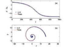
Here J (∞ ) is the exchange energy at infinity, λ the strength of the pinning force, and ξ the range of the pinning center. The spatial profile of the exchange energies are chosen to be Gaussian with the local maximum at the origin, because it is proved by the authors that the local maximum of J and D could lower the energy of an skyrmion, thus pins it. Dynamically speaking, when a skyrmion is put near the pinning center, it will feel the pinning force and moves circularly to the pinning center. This motion could be explained by the Thiele theory that we have introduced previously. The pinning force is centripetal, and the skyrmion tends to move perpendicularly to the external force. Thus without damping, the skyrmion will undergo a circular motion, with its distance to the pinning center unchanged. But in reality, any material has damping, thus another tendency to move toward the pinning center occurs. The combination of the above two tendencies makes the skyrmion do circular motion, with its distance to the pinning center smaller and smaller, and finally it stays at the pinning center (Fig. 9).
 | Fig. 9. The pinning process of an isolated skyrmion near a pinning center. (a) The system energy decreases with time because of the Gilbert damping. (b) The trajectory of the skyrmion during the pinning process. It undergoes a circular motion, which is a combined effect of the effective Lorentz force and the damping force.[12] |
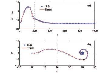 | Fig. 10. The depinning process of a skyrmion via an electric current pulse. (a) During the application of the current t=0– 200, the system energy exceeds the pinning energy; after that the system energy decreases with time because of the Gilbert damping. (b) The depinning– pinning trajectory. There are two pinning centers in the simulation, one at (0, 0) and the other at (40, 0). The skyrmion is depinned from (0, 0) and then pinned again at (40, 0). The black dot shows the position of the skyrmion when the current stops at t=200.[12] |
When a skyrmion stays in one of the pinning centers inside the pinning center lattice, it is possible to depin it by exerting a short-time electric current pulse. The depinned skyrmion will move toward another pinning center, and be pinned again (Fig. 10). This process is the two-dimensional generalization of the magnetic domain-wall racetrack memory. The depinning threshold is found to be proportional to the pinning strength λ , with an estimated value to be 108 A· m− 2. Physically speaking, the local maximum of the exchange energy could be achieved by engineering the local density of itinerant electrons in the material. The authors proposed to use nano-patterned metal grains on top of the chiral magnetic thin film to provide extra itinerant electrons. We note that such kind of nano-patterning has been used to assemble a skyrmion lattice even without the DM interaction.[106]
4.4. The collective mode of skyrmion
The skyrmion consists of a large number (call it N) of spins, of which each has two degrees of freedom (θ and ϕ ). As a result, the skyrmion has 2N microscopic degrees of freedom resulting in 2N modes of motion. As we know, only several low-lying modes are important for a macroscopic object, and it is the same for the skyrmion. Up to now, people have found a number of low-lying internal modes of the skyrmion.
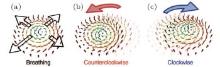
The first study of the internal modes of the skyrmion is reported by Japanese theorist Mochizuki. Utilizing the numerical simulation of the LLE, he found three internal modes of the skyrmion crystal, which could be excited by an applied ac magnetic field.[15] The three modes, by their real space configurations, are named as the breathing mode, the clockwise (CW) mode, and the counterclockwise (CCW) mode (Fig. 11). In the breathing mode, each skyrmion in the skyrmion crystal changes its size periodically in time, maintaining the cylindrical symmetry; in the CW (CCW) mode, the center-of-mass of each skyrmion moves clockwise (counterclockwise) around the equilibrium position periodically with time. These modes are verified experimentally by Onose et al. by microwave absorption experiment.[107]
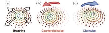 | Fig. 11. Three collective modes of the skyrmion crystal discovered by Mochizuki: (a) the breathing mode, (b) the counterclockwise rotation mode, (c) the clockwise rotation mode.[80] |
As we know, the excited mode in a continuum depends sensitively on the symmetry of the perturbation. The ac magnetic field could excite these modes because of the symmetry of the Zeeman term HZ = − ∑ iBi(t)· Si. In the breathing mode, the magnetic field is Bi(t) = [B0+B1sin(ω t)]ẑ , with B0 the dc component (to stabilize the skyrmion crystal) and B1 the ac component (to excite the collective mode). This magnetic field has the same symmetry as the breathing mode, i.e., rotational invariant about the z axis. In the CW and CCW modes, the magnetic field is 
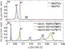
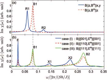
The three modes discovered by Mochizuki are three members of a yet larger zoo of internal modes of the skyrmion crystal. Other internal modes of the skyrmion could be excited by external perturbations with other symmetries. Liu et al. found that in the multiferroic material Cu2OSeO3, five modes could be excited by ac electric fields.[13] In this particular material, the electric field couples to the spin degree of freedom through the magnetoelectric coupling Hamiltonian
 |
This Hamiltonian has the cubic symmetry. If we fix the directions of the applied fields, the cubic symmetry is reduced to its subgroups. In the cases of B∥ [001] and E∥ [001] (case I), B∥ [110] and E∥ [001] (case II), and B∥ [111] and E∥ [111] (case III), this Hamiltonian could be rewritten (after a rotation of the axis: 
 |
In these three cases, the perturbations have different symmetries. The excited modes in case I are the elliptical mode (E) and the square modes (X1 and X2); in case III there are the nodeless (B1) and the nodal (B2) breathing modes; case II contains all five modes (Fig. 12).
By systematically solving the linearized LLE near the equilibrium skyrmionic state, Lin et al. predicted more internal modes of the skyrmions.[16] Up to now, people already have a very clear understanding about the internal motion of the skyrmion by different approaches.[102, 108, 109]
5. The emergent electrodynamics
The emergent electrodynamics is a very interesting phenomenon in skyrmion physics. We had a brief introduction in the previous sections: when a spinful quasiparticle moves in a skyrmionic background, it will feel an effective magnetic field, which is proportional to the solid angle (per area) spanned by the background magnetic moments. The effective charge that couples to the effective field is just the spin of the quasiparticle, for spin half we have
 |
This is the result of a static magnetic background. For a dynamic magnetic background, there will also be a corresponding effective electric field
 |
The electric field is also caused by the Berry phase picked up during the motion of the quasiparticle.[17, 18]
For a coupled system with skyrmions and conducting electrons, if we are only interested in the macroscopic transport property (with much larger length scale than the skyrmion radius), then we could replace the microscopic spin degrees of freedom (by which the skyrmions are constituted) by a macroscopic emergent electromagnetic field. This is the meaning of the emergence in this context.
5.1. The emergent Faraday's law
In 2012, the group of Pfleiderer and Rosch et al. discovered the emergent Faraday's law in the skyrmion crystal phase of the chiral magnet MnSi.[18] They measured the Hall resistivity in this material and found that it has a considerable suppression in the case of larger applied electric current (Fig. 13). They performed the experiment in different temperatures and magnetic fields, and found that the region with Hall signal suppression, in the temperature– magnetic field plane, is the same as the A-phase in the magnetic phase diagram. The suppression of Hall signal could be explained by the emergent electrodynamics as follows.
In the case of small current, the skyrmions are pinned by the disorders in the material, so that the skyrmion crystal can not be pushed to move along with the applied current. In the view of the conducting electrons, the background magnetic structure is static without motion, so there will only be an effective magnetic field, but no effective electric field. In this case, the Hall signal has three origins, 1) the normal Hall effect from the applied external magnetic field, 2) the anomalous Hall effect from the z component of the magnetic background, and 3) the topological Hall effect (as termed in the literature) from the emergent magnetic field.[17, 19, 20, 53, 93]
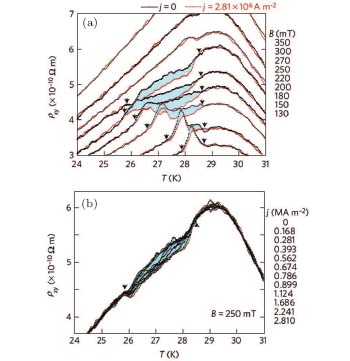 | Fig. 13. The emergent Faraday's law. (a) When there is no applied current, the skyrmion crystal is static, and the Hall signal is plotted in black curve. When there is a large enough applied current, the skyrmion crystal flows with the current, and the Hall signal is suppressed because of the emergent electric field induced by the emergent Faraday's law. (b) The temperature range of the suppression of the Hall signal is the same as that of the skyrmion crystal phase in the magnetic phase diagram.[18] |
When the current is larger, the skyrmion crystal is depinned from the disorders, and moves along the applied current with the drift velocity vd. Thus the conducting electrons feel an additional emergent electric field, which satisfies the emergent Faraday’ s law Eeff = − vd × Beff. This law could be proved as follows:
 |
In the proof, we have again used the condition for collective motion, i.e., 
From the above reasoning, we know that the skyrmion, when moving along the current, will supply a perpendicular electric field. Thus the total force acting on the conducting electron is
 |
where E is the applied electric field, FH is the Hall force from normal and anomalous Hall effects, and the last term qeff(v− vd)× Beff is the total force from the emergent electromagnetic fields. It is clear that if vd≠ 0, the Hall force from the emergent electric field will partially cancel that from the emergent magnetic field.
5.2. The topological non-Fermi liquid
The material system MnSi is one of the most important systems in the chiral magnetic family. Before the discovery of the skyrmion crystal, it has also been intensively studied because of the non-Fermi liquid (NFL) phase under high pressures.[110– 114] The NFL property of MnSi manifests in the transport behavior. For a normal Fermi liquid, the resistivity is proportional to the square of the temperature ρ ∝ T2. This could be understood as follows. In low temperatures, one of the origin of resistivity is the electron– electron scattering. At temperature T, only an energy shell in the order of kBT around the Fermi surface is active for quasiparticle scattering. So the two-particle scattering phase space is proportional to T2, which leads to the T2 law of resistivity. Under low pressures, the resistivity of MnSi satisfies the T2 law; however, under a high pressure, the resistivity is proportional to T3/2, which shows a significant deviation from the T2 law. The origin of this NFL behavior has been a challenge to both experimental and theoretical physics.
MnSi has many facets, the NFL behavior belongs to the charge counterpart, while the chiral magnetic behavior belongs to the magnetic counterpart. It is important to realize that these two counterparts are inseparable. Under high pressures, when the charge degree of freedom enters the NFL phase, the magnetic order is suppressed simultaneously.[115, 116] Back in 2004, using the neutron scattering experiment, Pfleiderer et al. found that there is a partial order in the NFL phase of MnSi, meaning that there is a magnetic order in very short time and small length scales, which could not be detected by static measurements.[115]
Many theorists are inspired by the notion of the partial order. Binz et al. first conjectured that the partial magnetic order might be constituted by skyrmions; [117, 118] then in 2010, Belitz et al. generalized their theory for itinerant magnets and derived the T3/2 law. They assumed the existence of columnar skyrmionic orders, with no requirement on long range correlation, i.e., isolated skyrmions are enough to lead to the NFL behavior.[119– 121] Note that the skyrmions in the NFL phase have very short lifetime, to be distinguished from the stabilized skyrmions that have been discussed previously.
The latest progress on the NFL behavior again comes from the Pfleiderer group.[122, 123] Inspired by the recent discovery of emergent electrodynamics in MnSi, they studied the emergent electrodynamic phenomena in the NFL phase of MnSi, and found that under high pressures, when the magnetic order is suppressed, the charge still shows the topological Hall effect. More importantly, the region of the NFL and that of the topological Hall effect coincide with each other in the temperature– field– pressure phase diagram (Fig. 14). Based on this experimental progress, Watanabe et al. proposed a theory of emergent quantum-electrodynamics, taking into account the conducting electrons and the background skyrmionic magnetic structure.[124] In this theory, the skyrmions, with their topological properties and dynamical modes of motion, are represented by emergent electromagnetic fields. The coupling form between the electrons and the emergent fields is assumed to be the “ minimal coupling” . The authors calculated the self-energy effect of the electrons in the background fields, and derived the T3/2 behavior of the resistivity. It is to be noted that in this theory, a long rang ordered skyrmion state, which contradicts to the partial order, is assumed at the beginning. In this sense, a theory that could fully explain the topological NFL in MnSi is still to be expected.
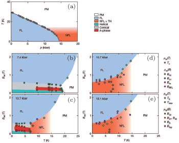 | Fig. 14. The temperature– magnetic field– pressure phase diagram of MnSi. Under high pressures, the magnetic order is suppressed, leaving place for the non-Fermi liquid phase. It is to be noted that the region of the non-Fermi liquid phase coincides with that of the topological Hall effect (plotted in orange). This means that the skyrmions with short lifetime exist in the non-Fermi liquid phase, forming the partial magnetic order.[122] |
5.3. The emergent electrodynamics of magnons
We have been discussing the emergent electrodynamics of the spin 1/2 quasiparticle of electrons. In fact the emergent electrodynamics has a wider range of application. Recently, some theorists start to discuss the possibility of emergent electrodynamics for spin 1 quasiparticles. In condensed matter systems, the magnons, or quantized spin waves, are typical spin 1 objects. The magnon state describes the deviation of the magnetic order from the equilibrium state or the decrease of the z-direction spin quantum number ms. In this sense, the direction of magnon is opposite to the local magnetic background, or the effective charge of magnon is qeff = − 1.
The first study of emergent electrodynamics of magnons is published by Hoogdalem et al.[21] They approached this issue by studying the thermal Hall effect of the skyrmion crystal. In an insulating magnet, the heat is transferred by a current of magnons, against the applied temperature gradient. Because the background magnetic state has nonzero topological number, and the moving magnons all have spin, so the magnons feel an emergent Lorentz force and a heat current perpendicular to the temperature gradient is induced. This is very similar to the topological Hall effect of electrons, only the spin of the quasiparticle is different.
Following Hoogdalem's work, Kong et al. discussed the counter force on the skyrmions from the magnons, and found that an isolated skyrmion will be pushed by the magnon current, and undergoes a rigid motion.[22] Lin et al. and Iwasaki et al. have found similar results.[23, 24] The approach of Iwasaki et al. is particularly inspiring. They mapped the magnon– skyrmion scattering problem to the Aharonov– Bohm effect of a charged particle passing through a magnetic flux. The magnon carries an emergent charge of − 1, and the skyrmion gives an emergent flux of 4π ħ , so there is a one-to-one correspondence between the two seemingly distinct physical situations. Detailed simulations of the LLE show that, when passing through the skyrmion, the magnon plane wave acquires a skew angle. This angle changes the momentum of the magnon, so the conservation of momentum requires the skyrmion to move in a definite way (Fig. 15).
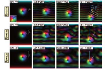 | Fig. 15. The magnon– skyrmion scattering process. The magnon current (shown as a plane wave) is generated from the lower region via an ac magnetic field. When the magnon current passes through the skyrmion, it acquires a skew angle, which proves the existence of an emergent magnetic field viewed by the magnons.[24] |
6. Conclusion and prospect
In chiral magnets, the magnetic skyrmions are localized stable objects, which are found in the equilibrium state of the magnets in certain temperature and applied fields. Materials with very different electromagnetic properties have been discovered to host the skyrmions, which makes it possible to probe the skyrmions in a variety of physical conditions. Being not only thermodynamically stable, the skyrmions are also very active for dynamic processes, it is possible to manipulate the skyrmions by spin polarized electric currents, external electromagnetic fields, and artificially introduced inhomogeneities of the material. The skyrmions couple to other quasiparticles via the emergent electrodynamics, which sheds new light on both fundamental physics and applications.
We acknowledge Han J H and Zhou Y for collaborations on the subject.
Reference
| 1 |
|
| 2 |
|
| 3 |
|
| 4 |
|
| 5 |
|
| 6 |
|
| 7 |
|
| 8 |
|
| 9 |
|
| 10 |
|
| 11 |
|
| 12 |
|
| 13 |
|
| 14 |
|
| 15 |
|
| 16 |
|
| 17 |
|
| 18 |
|
| 19 |
|
| 20 |
|
| 21 |
|
| 22 |
|
| 23 |
|
| 24 |
|
| 25 |
|
| 26 |
|
| 27 |
|
| 28 |
|
| 29 |
|
| 30 |
|
| 31 |
|
| 32 |
|
| 33 |
|
| 34 |
|
| 35 |
|
| 36 |
|
| 37 |
|
| 38 |
|
| 39 |
|
| 40 |
|
| 41 |
|
| 42 |
|
| 43 |
|
| 44 |
|
| 45 |
|
| 46 |
|
| 47 |
|
| 48 |
|
| 49 |
|
| 50 |
|
| 51 |
|
| 52 |
|
| 53 |
|
| 54 |
|
| 55 |
|
| 56 |
|
| 57 |
|
| 58 |
|
| 59 |
|
| 60 |
|
| 61 |
|
| 62 |
|
| 63 |
|
| 64 |
|
| 65 |
|
| 66 |
|
| 67 |
|
| 68 |
|
| 69 |
|
| 70 |
|
| 71 |
|
| 72 |
|
| 73 |
|
| 74 |
|
| 75 |
|
| 76 |
|
| 77 |
|
| 78 |
|
| 79 |
|
| 80 |
|
| 81 |
|
| 82 |
|
| 83 |
|
| 84 |
|
| 85 |
|
| 86 |
|
| 87 |
|
| 88 |
|
| 89 |
|
| 90 |
|
| 91 |
|
| 92 |
|
| 93 |
|
| 94 |
|
| 95 |
|
| 96 |
|
| 97 |
|
| 98 |
|
| 99 |
|
| 100 |
|
| 101 |
|
| 102 |
|
| 103 |
|
| 104 |
|
| 105 |
|
| 106 |
|
| 107 |
|
| 108 |
|
| 109 |
|
| 110 |
|
| 111 |
|
| 112 |
|
| 113 |
|
| 114 |
|
| 115 |
|
| 116 |
|
| 117 |
|
| 118 |
|
| 119 |
|
| 120 |
|
| 121 |
|
| 122 |
|
| 123 |
|
| 124 |
|