S. Nadeem, Rashid Mehmood, Noreen Sher Akbar. Partial slip effect on non-aligned stagnation point nanofluid over a stretching convective surface. Chinese Physics B, 2014, 24(1): 014702
Permissions
Partial slip effect on non-aligned stagnation point nanofluid over a stretching convective surface
S. Nadeema), Rashid Mehmooda)†, Noreen Sher Akbarb)
Department of Mathematics, Quaid-i-Azam University 45320, Islamabad 44000, Pakistan
DBS&H, CEME, National University of Sciences and Technology, Islamabad, Pakistan
The present study inspects the non-aligned stagnation point nano fluid over a convective surface in the presence of partial slip.Two types of base fluids namely water and kerosene are selected with Cu nanoparticles. The governing physical problem is presented and transformed into a system of coupled nonlinear differential equations using suitable similarity transformations. These equations are then solved numerically using midpoint integration scheme along with Richardson extrapolation via Maple. Impact of relevant physical parameters on the dimensionless velocity and temperature profiles are portrayed through graphs. Physical quantities such as local skin frictions co-efficient and Nusselt numbers are tabularized. It is detected from numerical computations that kerosene-based nano fluids have better heat transfer capability compared with water-based nanofluids. Moreover it is found that water-based nanofluids offer less resistance in terms of skin friction than kerosene-based fluid. In order to authenticate our present study, the calculated results are compared with the prevailing literature and a considerable agreement is perceived for the limiting case.
The notion of nanofluids has become a topic of global interest in the last few decades as they provide an effective way of improving heat transfer characteristics of fluids. It is expected that thermal conductivity of nanofluids is higher than that of common fluids.[1] Heat transfer fluids like water, oil, and glycols are extensively used in industrial and civil applications such as hot metal shears, [2] fire-resistance, air conditioning, electric cooling, etc. but they possess low thermal conductivity. In certain engineering processes like paper production, glass blowing, crystal growing, extrusion of plastic[3] and metal spinning, heat transfer rate at the stretching surface is dynamic since it is closely related to the quality of the final product. In order to overcome this deficiency, thermally conductive nano-meter sized particles (1– 100 nm) are suspended in the base fluid to accelerate the heat transfer rate. Choi[4] devised the notable concept of nanofluids. Wongwises et al.[5] presented a critical analysis of convective heat transfer nanofluids. Leon et al.[6] broadly decorated the applications of nanofluids. Some useful studies emphasizing the utility of nanofluids can be found in Refs. [7]– [10]. Nanofluid flows over stretching surface are a topic of intense study these days. A great number of researchers have conducted independent studies to discuss the flow behavior of nanofluids under certain physical situations, e.g., Bachok et al.[11] monitored the stagnation-point flow over a stretching/shrinking sheet in a nanofluid. Anderson[12] presented a novel study on slip flow past a stretching surface. In another article, Hill et al.[13] focused on the nano boundary layer equation with nonlinear Navier boundary condition. Zhang et al.[14] deliberated a useful analysis to study the effect of slip condition on the MHD stagnation-point over a power-law stretching sheet. Viscous flow over a shrinking sheet with a second-order slip flow model is presented by Aziz et al.[15] Wang[16] examined the viscous flow due to a stretching sheet with surface slip and suction. Mukhopadhyay et al.[17] estimated the effects of partial slip on boundary layer flow past a permeable exponential stretching taking into account the thermal radiation. Recently, Das[18] inspected the slip flow and convective heat transfer of nanofluids over a permeable stretching surface and concluded that the increase in the slip velocity and nanoparticle volume fraction consequently increases the thermal boundary layer thickness. Yazdi et al.[19] conferred the slip MHD liquid flow over nonlinear permeable stretching surface with chemical reaction. Pop et al.[20] piloted a valuable study to discuss the convective heat transfer in the flow of a water-based nanofluid over a stretching surface. Some noteworthy studies related to the present topic can be found in Refs. [21]– [35]. To the best of our knowledge, no one so far has discussed the non-aligned stagnation point nanofluid flow with partial slip and convective heat transfer over a stretching surface. Hence, our motivation is to discuss the partial slip effect on a nanofluid over a stretching convective surface when the fluid strikes the wall in an oblique manner.
2. Mathematical formulation
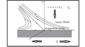
Consider the steady oblique stagnation point flow of a nano fluid over a stretching surface which strikes the surface at y = 0. Two types of base fluids namely water and kerosene are selected with Cu nanoparticles. The base fluid and the nanoparticles are in thermal equilibrium. Two forces of equal magnitude are applied in opposite directions to keep the surface stretched. The fluid lodges the entire half plane y > 0. It is presumed that the surface has temperature Tf, and free stream temperature T∞ .
Under these assumptions, the equations governing the flow and heat phenomenon are[9– 11, 20, 21]
where u* and v* are the velocity components along the co-ordinate axis respectively. T* is the temperature, υ nf is the effective kinematic viscosity, and α nf is the effective thermal diffusivity of nanofluid. The physical properties of nanofluids restricted to spherical nanoparticles can be stated as the cartel features of based fluids and nanoparticles in terms of particle volume fraction as follows:[20, 21]
where knf is the thermal conductivity, (ρ Cp)nf is the heat capacity, and Φ is the solid volume fraction of nanofluid.
where a, b, and c are positive constants with dimensions of inverse time, N is a slip constant, hf is the convective heat transfer coefficient, and c > 0 is the stretching rate. By using
where we have used the datum that f(y) behaves as (a/c)y+δ as y goes to infinity. Here δ represents the boundary layer displacements constant which needs to be computed.
Physical quantities of interest are the shear stress and local heat flux at the wall which are given by
The position xs of attachment of dividing streamline is determined by zero wall shear stress, i.e.,
One can observe that the point of stagnation is independent of particle volume fraction of nanoparticles.
3. Method of solution
The system of coupled non-linear ordinary differential equations along with the boundary conditions (21) is complicated in nature, so a numerical solution would be an obvious choice. Keeping this in mind, a very efficient computational software known as Maple 15 is used to obtain numerical results as well as graphical outputs. The governing system is solved numerically using the midpoint integration scheme along with Richardson's extrapolation.[27– 29] This involves the transformation of the governing system of equations into a set of first-order non-linear differential equations which are then conveniently integrated to achieve the required solutions. The problem of semi-infinite domain [0, ∞ ) is generously transformed into such appropriate finite domain of y, i.e., [0, y∞ ), where y∞ should be large enough that the numerical solutions would approach the asymptotic behavior at the infinite boundaries. A mesh size of Δ h = 0.001 was found enough for a convergence criterion of 10− 6 in almost all cases. In order to confirm the accuracy of our numerical solutions, results are obtained in the absence of nanoparticles, i.e., for the case of pure fluid when (Φ 0 = 0) and they are found to be in good agreement with those of Pop et al.[22] and Gupta et al.[25] (see Table 1).
Table 1.
Table 1.
Table 1. Comparison with the previous existing literature when λ = 0 = Φ
Table 1. Comparison with the previous existing literature when λ = 0 = Φ
4. Results and discussion
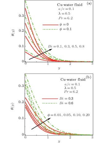
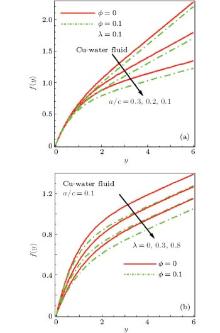
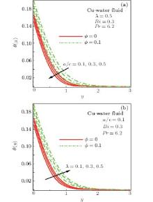
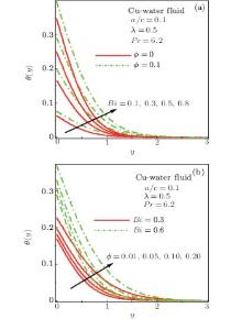
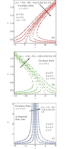
For the sake of analysis, we have conducted numerical computations against various values of stretching ratio a/c, slip parameter λ , and nanoparticle volumetric concentration on velocity and temperature profiles. Figures 2– 7 are plotted to highlight these effects. Figures 2 and 3 show the impact of stretching parameter a/c and slip parameter λ on normal flow f(y) and velocity profile f′ (y) for the case of pure fluid (Φ = 0) and nanofluid (Φ = 0). From Figs. 2(a) and 2(b), it is observed that the normal component of the flow f(y) increases with the increase in stretching ratio a/c, whereas it tends to decrease with increasing slip factor λ . Moreover, it is apparent that the normal component of the flow f(y) is higher in magnitude for the case of pure fluid when compared with the nanofluid. Figure 3(a) displays that the normal component of the velocity f′ (y) increases as we increase stretching ratio a/c and it is apparent in the boundary layer region. This is due to the fact that when stretching ratio a/c increases, it causes the free stream velocity ax of the external fluid to exceed the stretching velocity cx of the stretching surface. Figure 3(b) depicts that with the increase in slip parameter λ , the normal component of the velocity f′ (y) decreases. The physical reasoning behind it could be that when the slip factor is increased, it leads the fluid particles near the stretching surface to move swiftly which consequently decreases the normal fluid velocity. Figures 4(a) and 4(b) study the influence of stretching parameter a/c and slip parameter λ on tangential flow component h(y). It is easily noticeable from these figures that both these parameters have a positive influence on tangential flow component h(y). This is in good agreement with the physical situation because an increase in the stretching rate or increase in the slip factor ultimately favours the tangential flow due to its direction. Behavior of the tangential velocity component h′ (y) against stretching parameter a/c and slip factor λ is expressed through Figs. 5(a) and 5(b). It is found that tangential velocity h′ (y) rises with stretching parameter a/c. Further, nanoparticle volumetric concentration Φ causes an initial increase in the tangential velocity h(y) (see Fig. 5(a)). From Fig. 5(b), it is evident that an increase in the slip factor, leads to a reduction in tangential velocity h′ (y). In addition, it is also found that the magnitude of the tangential velocity h′ (y) is higher for the case of nanofluid within the boundary layer region when compared with the pure fluid. Figures 6 and 7 give us an idea about how the temperature profile θ (y)reacts against various values of stretching parameter a/c, slip parameter λ , and nanoparticle volumetric concentration Φ . Figure 6(a) indicates that when we increase the stretching parameter a/c, temperature profile θ (y) drops. Furthermore, it also appears that with insertion of nanoparticles, magnitude of temperature profile θ (y) rises in comparison to the pure fluid. This is due to the inclusion of Cu nanoparticles; these tiny nano particles have a lot higher thermal conductivity and comparatively low specific heat in comparison to the base fluid which consequently gives higher temperature at the surface. Figure 6(b) describes that slip parameter λ causes an increase in the temperature profile θ (y). Figures 6(a) and 6(b) specify that with the increase in Biot number Bi and nanoparticle volumetric concentration Φ , temperature profile θ (y) rises substantially. Since Biot number Bi involves the heat transfer coefficient so an increase in Biot number results in an increase in heat transfer coefficient which consequently enhances the fluid temperature θ (y). It can also be perceived that θ (y) is higher for nanofluid than pure fluid, close to the stretching convective surface. Finally the streamline pattern of the present problem for several shears in the flow is traced through Figs. 8(a)– 8(c). It is found that streamlines are tilted towards the left side of the origin for positive shear rate and it falls on the right side when the value of shear rate is taken to be negative. Moreover the streamline Ψ = 0.0 meets the wall at x = xs, the point of stagnation.
Fig. 8. Streamline patterns for γ = − 5.0 (a), γ = +5.0 (b), and γ = 0.0 (c).
Table 2 gives the thermo physical properties of water- and kerosene-based fluids with selected Cu nanoparticles.[9– 11] Tables 1, 3, 4 are set to classify the influence of stretching ratio a/c, slip parameter λ , Biot number Bi and nanoparticles volumetric concentration Φ on local skin friction and heat flux. Table 1 confirms that our present results are in good agreement with those of Pop et al.[22] and Gupta et al.[25] for the case of pure fluid i.e., when Φ = 0. Tables 3 and 4 are developed to compute the local skin frictions and heat flux at the stretching convective surface for water- and kerosene-based fluids respectively. These are some of the key findings. First of all, it is noticeable from both these tables that boundary layer displacement constant δ continuously decreases with the increase in stretching parameter a/c, slip parameter λ , and nanoparticle volumetric concentration. Besides, a slightly greater value of boundary layer displacement constant δ is recorded for water-based fluid than kerosene-based fluid. This is perhaps due to the fact that kerosene-based fluids are more viscous in nature than water-based fluids and offer more resistance to the flow. It is also obvious from these tables that increasing nanoparticle volumetric concentration results in an increase in both normal and tangential components of the local skin friction for water as well as kerosene-based fluid. Increasing stretching parameter a/c descents the normal skin friction component while it raises the tangential component of the local skin friction for both types of base fluids. The tabulated results also revealed that when we increase the slip parameter λ local skin friction components gradually declines. This has clear physical justification as increased slip causes the stretched surface to offer less resistance which consequently decays local skin friction and heat transfer rate. Heat transfer rate at the stretching convective surface increases when stretching ratio a/c, Biot number Bi, and nanoparticles volumetric concentration increases for water- and kerosene-based fluids while it portrays a decreasing behavior for the slip parameter λ . From these results it can be perceived that nanoparticles can certainly improve the heat transfer rate at the surface. Moreover, it is also observed that for large values of Biot number Bi, local heat flux at the wall also increases which is clearly because larger Biot numbers mean higher heat transfer co-efficients which helps in better heat transfer rate at the stretching convective surface. Further it is worth mentioning here that kerosene-based fluid has shown better heat transfer ability compared to the water-based fluid. These results are well justified with the fact that kerosene-based fluid has less thermal conductivity and higher Prandtl number Pr compared with traditional water-based fluid.
Table 2.
Table 2.
Table 2. Thermal characteristics of water and kerosene with Cu nanoparticles.[9, 11, 20]
Physical properties
Kerosene
Water
Cu
ρ /(kg/m3)
783
997.1
8933
Cp/(J/kg)
2090
4179
385
k/(W/m)
0.15
0.613
400
Pr
15.6
6.2
–
Table 2. Thermal characteristics of water and kerosene with Cu nanoparticles.[9, 11, 20]
Table 3.
Table 3.
Table 3. Numerical values of local skin friction co-efficient and local heat flux for Cu– water-based fluid.
Φ
a/c
λ
Bi
δ
0.01
0.1
0.2
0.3
0.682579
0.787713
0.265072
0.260436
0.10
0.587198
1.109253
0.335254
0.326348
0.20
0.563879
1.530281
0.449593
0.413112
0.10
0.1
0.2
0.3
0.587198
1.109253
0.335254
0.326348
0.3
0.364328
0.968819
0.697707
0.329180
0.5
0.220759
0.756543
0.856601
0.332380
0.1
0.1
0.1
0.3
0.625587
1.265146
0.339529
0.328772
0.3
0.555491
0.990752
0.330553
0.324231
0.5
0.505266
0.820951
0.320837
0.320645
0.1
0.1
0.5
0.1
0.123075
0.2
0.228817
0.3
0.320645
Table 3. Numerical values of local skin friction co-efficient and local heat flux for Cu– water-based fluid.
Table 4.
Table 4.
Table 4. Numerical values of local skin friction co-efficient and local heat flux for Cu-kerosene-based fluid.
Φ
a/c
λ
Bi
δ
0.01
0.1
0.2
0.3
0.674154
0.794626
0.265003
0.282084
0.10
0.546591
1.163893
0.334650
0.361085
0.20
0.511546
1.632064
0.448432
0.468682
0.10
0.1
0.2
0.3
0.546591
1.163893
0.334650
0.361085
0.3
0.338032
1.016275
0.692649
0.362108
0.5
0.204327
0.793264
0.847970
0.363424
0.1
0.1
0.1
0.3
0.584221
1.336072
0.339269
0.362595
0.3
0.515771
1.034593
0.329598
0.359763
0.5
0.467362
0.851543
0.319243
0.357508
0.1
0.1
0.5
0.1
0.128226
0.2
0.247064
0.3
0.357508
Table 4. Numerical values of local skin friction co-efficient and local heat flux for Cu-kerosene-based fluid.
5. Conclusions
The present study provides the influence of partial slip on non-aligned stagnation point flow of a nanofluid over a stretching convective surface. The main findings of the study can be summarized as follows.
Within the boundary layer region, normal flow and velocity decreases with the increase in the slip parameter while it increases with the increase in stretching ratio.
Effect of stretching ratio and slip parameter on tangential flow is positive, whereas tangential velocity responded in an opposite manner for both these parameters.
Boundary layer displacement constant δ tends to decrease with an increase in stretching ratio, slip parameter and nanoparticle volume fraction.
Insertion of nanoparticles drops both normal and tangential velocity components and increases the temperature profile.
With an increase in nanoparticle volume fraction, local skin friction and heat flux at the wall increases. Moreover, kerosene-based fluids have shown higher heat transfer rates compared with the water-based fluids.
... [1] Heat transfer fluids like water, oil, and glycols are extensively used in industrial and civil applications such as hot metal shears,[2] fire-resistance, air conditioning, electric cooling, etc ...
1
1983
0.0
0.0
... [1] Heat transfer fluids like water, oil, and glycols are extensively used in industrial and civil applications such as hot metal shears,[2] fire-resistance, air conditioning, electric cooling, etc ...
1
1970
0.0
0.0
... In certain engineering processes like paper production, glass blowing, crystal growing, extrusion of plastic[3] and metal spinning, heat transfer rate at the stretching surface is dynamic since it is closely related to the quality of the final product ...
1
1995
0.0
0.0
... Choi[4] devised the notable concept of nanofluids ...
Abstract A nanofluid is a suspension of ultrafine particles in a conventional base fluid which tremendously enhances the heat transfer characteristics of the original fluid. Furthermore, nanofluids are expected to be ideally suited in practical applications as their use incurs little or no penalty in pressure drop because the nanoparticles are ultrafine, therefore, appearing to behave more like a single-phase fluid than a solid–liquid mixture. About a decade ago, several published articles focused on measuring and determining the effective thermal conductivity of nanofluids, some also evaluated the effective viscosity. There are only a few published articles on deriving the forced convective heat transfer of nanofluids. The purpose of this article is to summarize the published subjects respect to the forced convective heat transfer of the nanofluids both of experimental and numerical investigation.
... [5] presented a critical analysis of convective heat transfer nanofluids ...
1
2010
0.0
0.0
... [6] broadly decorated the applications of nanofluids ...
Abstract This paper reports an experimental work on the convective heat transfer of nanofluids, made of γ-Al 2 O 3 nanoparticles and de-ionized water, flowing through a copper tube in the laminar flow regime. The results showed considerable enhancement of convective heat transfer using the nanofluids. The enhancement was particularly significant in the entrance region, and was much higher than that solely due to the enhancement on thermal conduction. It was also shown that the classical Shah equation failed to predict the heat transfer behaviour of nanofluids. Possible reasons for the enhancement were discussed. Migration of nanoparticles, and the resulting disturbance of the boundary layer were proposed to be the main reasons.
... Under these assumptions, the equations governing the flow and heat phenomenon are[9#cod#x2013 ...
Abstract An analysis is carried out to study the steady two-dimensional stagnation-point flow of a nanofluid over a stretching/shrinking sheet in its own plane. The stretching/shrinking velocity and the ambient fluid velocity are assumed to vary linearly with the distance from the stagnation point. The similarity equations are solved numerically for three types of nanoparticles, namely copper, alumina, and titania in the water-based fluid with Prandtl number Pr = 6.2. The skin friction coefficient, Nusselt number, and the velocity and temperature profiles are presented graphically and discussed. Effects of the solid volume fraction φ on the fluid flow and heat transfer characteristics are thoroughly examined. Different from a stretching sheet, it is found that the solutions for a shrinking sheet are non-unique.
1. Department of Mathematics and Institute for Mathematical Research, Universiti Putra Malaysia, 43400, UPM Serdang, Selangor, Malaysia 2. School of Mathematical Sciences, Faculty of Science and Technology, Universiti Kebangsaan Malaysia, 43600, UKM Bangi, Selangor, Malaysia 3. Faculty of Mathematics, University of Cluj, CP 253, 3400, Cluj, Romania
... [11] monitored the stagnation-point flow over a stretching/shrinking sheet in a nanofluid ...
... 11,20,21](1)
... 11] Tables 1, 3, 4 are set to classify the influence of stretching ratio a/c, slip parameter #cod#x03BB ...
The slip-flow of a Newtonian fluid past a linearly stretching sheet is considered. The partial slip is controlled by a dimensionless slip factor, which varies between zero (total adhesion) and infinity (full slip). An exact analytical solution of the governing Navier-Stokes equation is found, which is formally valid for all Reynolds numbers.
1.Department of Applied Mechanics, Thermodynamics and Fluid Dynamics The Norwegian University of Science and Technology 7491 Trondheim Norway
... Anderson[12] presented a novel study on slip flow past a stretching surface ...
1
2007
1.05
0.0
... [13] focused on the nano boundary layer equation with nonlinear Navier boundary condition ...
The steady two-dimensional magnetohydrodynamic stagnation flow towards a nonlinear stretching surface is studied. The no-slip condition on the solid boundary is replaced with a partial slip condition. A scaling group transformation is used to get the invariants. Using the invariants, a third-order ordinary differential equation corresponding to the momentum is obtained. An analytical solution is obtained in a series form using a homotopy analysis method. Reliability and efficiency of series solutions are shown by the good agreement with numerical results presented in the literature. The effects of the slip parameter, the magnetic field parameter, the velocity ratio parameter, the suction velocity parameter, and the power law exponent on the flow are investigated. The results show that the velocity and shear stress profiles are greatly influenced by these parameters.
Department of Mathematics and Mechanics, University of Science and Technology Beijing, Beijing 100083, P. R. China
The steady two-dimensional magnetohydrodynamic stagnation flow towards a nonlinear stretching surface is studied. The no-slip condition on the solid boundary is replaced with a partial slip condition. A scaling group transformation is used to get the invariants. Using the invariants, a third-order ordinary differential equation corresponding to the momentum is obtained. An analytical solution is obtained in a series form using a homotopy analysis method. Reliability and efficiency of series solutions are shown by the good agreement with numerical results presented in the literature. The effects of the slip parameter, the magnetic field parameter, the velocity ratio parameter, the suction velocity parameter, and the power law exponent on the flow are investigated. The results show that the velocity and shear stress profiles are greatly influenced by these parameters.
... [14] deliberated a useful analysis to study the effect of slip condition on the MHD stagnation-point over a power-law stretching sheet ...
Abstract In this paper, viscous flow over a shrinking sheet is solved analytically using a newly proposed second order slip flow model. The closed solution is an exact solution of the full governing Navier–Stokes equations. The solution has two branches in a certain range of the parameters. The effects of the two slip parameters and the mass suction parameter on the velocity distribution are presented graphically and discussed. For certain combinations of the slip parameters, the wall drag force can decrease with the increase of mass suction. These results clearly show that the second order slip flow model is necessary to predict the flow characteristics accurately.
... [15] Wang[16] examined the viscous flow due to a stretching sheet with surface slip and suction ...
1
2009
0.0
0.0
... [15] Wang[16] examined the viscous flow due to a stretching sheet with surface slip and suction ...
Abstract An analysis is presented to describe the boundary layer flow and heat transfer towards a porous exponential stretching sheet. Velocity and thermal slips are considered instead of no-slip conditions at the boundary. Thermal radiation term is incorporated in the temperature equation. Similarity transformations are used to convert the partial differential equations corresponding to the momentum and heat equations into highly non-linear ordinary differential equations. Numerical solutions of these equations are obtained by shooting method. It is found that the fluid velocity and temperature decrease with increasing slip parameter. Temperature is found to decrease with an increase of thermal slip parameter. Thermal radiation enhances the effective thermal diffusivity and the temperature rises.
1. Department of Mathematics, The University of Burdwan, Burdwan, 713104, West Bengal, India 2. Department of Mechanical Engineering, Cleveland State University, Cleveland, OH, 44115, USA
... [17] estimated the effects of partial slip on boundary layer flow past a permeable exponential stretching taking into account the thermal radiation ...
2
2012
1.675
0.0
... Recently, Das[18] inspected the slip flow and convective heat transfer of nanofluids over a permeable stretching surface and concluded that the increase in the slip velocity and nanoparticle volume fraction consequently increases the thermal boundary layer thickness ...
... The appropriate boundary conditions are[18, 22](6)
1
2011
2.315
0.0
... [19] conferred the slip MHD liquid flow over nonlinear permeable stretching surface with chemical reaction ...
Abstract An analysis is carried out to study the convective heat transfer in a nanofluid flow over a stretching surface. In particular, we focus on Ag–water and Cu–water nanofluids, and investigate the effects of the nanoparticle volume fraction on the flow and heat transfer characteristics under the influence of thermal buoyancy and temperature dependent internal heat generation or absorption. The numerical results indicate that an increase in the nanoparticle volume fraction will decrease the velocity boundary layer thickness while increasing the thermal boundary layer thickness, even in the presence of free convection currents and internal heat generation. Meanwhile, the presence of nanoparticles results in an increase in the magnitude of the skin friction along the surface and a decrease in the magnitude of the local Nusselt number. Such effects are found to be more pronounced in the Ag–water solution than in the Cu–water solution; indeed, the Ag–water solution decreases the boundary layer thickness more than that of the Cu–water solution.
... [20] piloted a valuable study to discuss the convective heat transfer in the flow of a water-based nanofluid over a stretching surface ...
... 11,20,21](1)
... The physical properties of nanofluids restricted to spherical nanoparticles can be stated as the cartel features of based fluids and nanoparticles in terms of particle volume fraction as follows:[20, 21](5)
3
1904
2.891
0.0
... [21]#cod#x2013 ...
... 11,20,21](1)
... The physical properties of nanofluids restricted to spherical nanoparticles can be stated as the cartel features of based fluids and nanoparticles in terms of particle volume fraction as follows:[20, 21](5)
Abstract In the past, considerable attention has been given to the study of stagnation-point flows since they appear in many engineering and industrial applications. In some problems, flow is stagnated by a solid wall, while in others a free stagnation-point or line exists interior to the fluid domain. In this paper, the steady two-dimensional stagnation-point flow of a viscoelastic second-grade fluid over a stretching surface with heat transfer is examined. It is assumed that the fluid impinges on the wall obliquely. Using similarity variables, the governing partial differential equations are transformed into a set of three non-dimensional ordinary differential equations. These equations are then solved numerically using a quasi-linearization technique. It is shown that a boundary layer is formed when the stretching velocity of the surface is less that the inviscid free-stream velocity and velocity at a point increases with the increase in the elasticity of the fluid. It is also found that the temperature at a point decreases with increase in the elasticity of the fluid. The reported results are in good agreement with the available published work in the literature.
... The appropriate boundary conditions are[18, 22](6)
Abstract The influence of partial slip, thermal radiation and temperature dependent fluid properties on the hydro-magnetic fluid flow and heat transfer over a flat plate with convective surface heat flux at the boundary and non-uniform heat source/sink is studied. The transverse magnetic field is assumed as a function of the distance from the origin. Also it is assumed that the fluid viscosity and the thermal conductivity vary as an inverse function and linear function of temperature respectively. Using the similarity transformation, the governing system of non-linear partial differential equations are transformed into similarity non-linear ordinary differential equations and are solved numerically using symbolic software MATHEMATICA 7.0. The numerical values obtained within the boundary layer for the dimensionless velocity, temperature, skin friction coefficient and the Nusselt number are presented through graphs and tables for several sets of values of the parameters. The effects of various physical parameters on the flow and heat transfer characteristics are discussed from the physical point of view.
1. Department of Mathematics, Kalyani Government Engineering College, Kalyani, Nadia, West Bengal, 741235, India
Steady two-dimensional stagnation-point flow of an incompressible viscous fluid over a flat deformable sheet is investigated when the sheet is stretched in its own plane with a velocity proportional to the distance from the stagnation-point. It is shown that for a fluid of small kinematic viscosity, a boundary layer is formed when the stretching velocity is less than the free stream velocity and an inverted boundary layer is formed when the stretching velocity exceeds the free stream velocity. Temperature distribution in the boundary layer is found when the surface is held at constant temperature and surface heat flux is determined.
1.Department of Mathematics Indian Institute of Technology Kharagpur-721 302, India IN
... [25] (see Table#cod#x00A0 ...
... [25] for the case of pure fluid i ...
1
2012
0.0
0.0
1
1995
0.0
0.0
... [27#cod#x2013 ...
1
1998
5.952
0.0
1
2013
0.0
0.0
... 29] This involves the transformation of the governing system of equations into a set of first-order non-linear differential equations which are then conveniently integrated to achieve the required solutions ...
Based on the binary Bell polynomials, the bilinear representation, bilinear Bäcklund transformation and the Lax pair for the dissipative (2+1)-dimensional Ablowitz–Kaup–Newell–Segur (AKNS) equation are obtained. Moreover, the infinite conservation laws are also derived.
1 Business School, Shandong University of Political Science and Law, Jinan 250014 2 School of Mathematical Sciences, Liaocheng University, Liaocheng 252059
Effects of an ultra-strong magnetic field on electron capture rates for Co-55 are analyzed in the nuclear shell model and under the Landau energy levels quantized approximation in the ultra-strong magnetic field, and the electron capture rates on 10 abundant iron group nuclei at the surface of a magnetar are given. The results show that electron capture rates on Co-55 are increased greatly in the ultra-strong magnetic field, by about 3 orders of magnitude generally. These conclusions play an important role in future study of the evolution of magnetars.
Du Jun 1 ;Li Ping-Ping 1 ;Luo Xia 1,2 ;
Effects of ultra-strong magnetic field on electron capture rates for 55 Co are analyzed in the nuclear shell model and under the Landau energy levels quantized approximation in the ultra-strong magnetic field, and the electron capture rates on 10 abundant iron group nuclei at the surface of magnetar are given. The results show that electron capture rates on 55 Co are increased greatly in the ultra-strong magnetic field, by about 3 orders of magnitude generally. These conclusions play an important role in future studying the evolution of magnetar.
1
2013
0.0
0.0
1
2014
0.673
0.0
... [35] ...
1
2014
0.673
0.0
Partial slip effect on non-aligned stagnation point nanofluid over a stretching convective surface


