


All-fiber optical modulator based on no-core fiber and magnetic fluid as cladding*
Cite this Article
Chen Yao-Fei, Han Qun, Liu Tie-Gen. All-fiber optical modulator based on no-core fiber and magnetic fluid as cladding* . Chinese Physics B, 2015, 24(1): 014214 
Permissions
All-fiber optical modulator based on no-core fiber and magnetic fluid as cladding*
Corresponding author. E-mail: hanqun@tju.edu.cn
Corresponding author. E-mail: tgliu@tju.edu.cn
Project supported by the Natural Science Foundation of Tianjin City, China (Grant No. 13JCYBJC16100), the National Natural Science Foundation of China (Grant No. 61107035), the National Key Scientific Instrument and Equipment Development Project of China (Grant No. 2013YQ03091502), and the National Basic Research Program of China (Grant Nos. 2010CB327802 and 2010CB327806).
Abstract
An all-fiber optical modulator, which is composed of a piece of no-core fiber spliced between two sections of single-mode fibers and uses magnetic fluid (MF) as the cladding of the no-core fiber section, is proposed and investigated experimentally. Due to the tunable refractive index and absorption coefficient of MF, the output intensity can be modulated by controlling an applied magnetic field. The dependences of the modulator’s temporal response on the working wavelength, the magnetic field strength ( H), and the MF’s concentration are investigated experimentally. The results are explained qualitatively by the dynamic response process of MF under the action of a magnetic field. The findings are helpful for optimizing this kind of modulator.
Keyword:
42.81.–i; 42.81.Qb; 75.50.Mm; optical fiber; optical modulator; no-core fiber; magnetic fluid
1. Introduction
Magnetic fluid (MF) is a kind of stable colloidal mixture of magnetic nano-particles dispersing in a suitable fluid carrier. MF possesses both the features of the magnetism of a solid ferromagnetic matter and the fluid behavior of a liquid matter.[1, 2] Originating from the motion and aggregation of magnetic particles under the action of a magnetic field, [3– 7] MF shows various attractive magneto-optical properties including tunable refractive index (RI), [8] magnetically controllable birefringence, [9] tunable absorption coefficient, [10] etc. Thus, many MF-based optical fiber devices have been proposed in recent years. These devices can be classified into two categories, i.e., magnetic field sensors[11– 13] and optical modulators, [14– 19] according to their functions. MF-based magnetic field sensors have been proposed with fiber structures such as a photonic crystal fiber, [11] a microfiber knot resonator, [12] and a long-period fiber grating in a D-shaped fiber.[13] Similarly, MF-based modulators have also been realized by several different methods. Compared with the way the light passing through an MF film is directly modulated, [15, 16] the method that uses MF as the cladding of a fiber[17– 19] features a lower transmission loss because of the all-fiber structure. In Ref. [17] a modulator was realized by replacing the cladding of a piece of multimode fiber (MMF) with MF, whose RI at zero magnetic field was slightly smaller than that of the multimode core. The intensity of output light can be easily modulated by controlling the occurrence of total reflection at the interface between the fiber core and the MF through magnetic field. In this method, the RI of the MF must be finely designed to be slightly smaller than that of the MMF core. To eliminate this limitation, an evanescent absorption based modulator was proposed in Ref. [18], which consisted of a piece of tapered singlemode fiber (SMF) immersed in MF. However, the tapered SMF is fragile and reduces the robustness of the modulator. The same problem exists in the modulator based on a hollow fiber and MF as reported in Ref. [19].
In a previous study, we proposed a magnetic field sensor based on singlemode-no-core-singlemode fiber (SNS) structure and MF, which was demonstrated only under the action of a static magnetic field.[20] In this paper, its temporal response characteristics are investigated and an all-fiber modulator based on the SNS and MF is proposed and investigated experimentally. A piece of no-core fiber (NCF) is spliced between two sections of SMFs to form an SNS fiber structure. The MF is used to serve as the cladding of the NCF. The modulator not only features a low transmission loss because of the all-fiber structure, but also possesses the advantages of low cost, easy fabrication, and robustness, due to the SNS fiber structure. Because of the tunable RI and absorption coefficient of MF, the output intensity can be modulated by changing the applied magnetic field. The influences of the wavelength, magnetic field strength (H), and MF’ s concentration on the temporal response are investigated experimentally.
2. Working principle
Figure 1(a) shows the schematic configuration of the all-fiber modulator. It is fabricated by splicing a piece of NCF between two sections of SMFs and then sealed in a capillary tube which is filled with MF. The input light in the SMF has a fundamental mode field distribution. Considering the circular symmetry of the fibers and assuming that the SMF and NCF are ideally aligned, when the light launches into the NCF section, a series of modes {LP0m} will be excited. Because the MF is highly absorptive, the evanescent field in the vicinity of the interface between the NCF and MF will induce a non-negligible attenuation to the light field as it passes through the NCF.[20] Thus the transmittance at a wavelength λ can be described as
 |
where L is the length of the NCF; M is the total number of modes existing in the NCF; ci, β i, and γ i are the excitation coefficient, propagating constant, and evanescent absorption coefficient of the LP0i mode, respectively. Based on the evanescent field absorption theory in a multimode fiber, γ i can be given by[21]
 |
where α λ is the attenuation coefficient of the MF at λ ; nf and nc are the RIs of the MF and NCF, respectively; a is the radius of the NCF; θ c is the critical angle [θ c = sin– 1(nf/nc)]; and θ i = sin– 1(β i/k), where k = 2π nc/λ is the wave number.
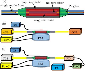 | Fig. 1. (a) Schematic of the all-fiber modulator. (b) and (c) Experimental setups. GS, Gaussmeter; ASE, amplified spontaneous emission; OSA, optical spectrum analyzer; PowC, power controller; EM, electromagnet; TLS, tunable light source; PD, photodetector; DAC, data acquisition card; PC, personal computer. |
When a magnetic field applied to the MF is switched on/off, the RI and α λ of MF will change due to the aggregation/dispersion of magnetic particles in the MF, which ultimately behaves as the changes of ci(j), β i(j), and γ i(j). Consequently, T(λ ) can be modulated by controlling the magnetic field, as shown in Eq. (1).
3. Experiment and discussion
We use a piece of NCF (Prime Optical Fiber Co.) with a length of 28 mm and a diameter of 61.5 μ m to fabricate an SNS structure by splicing it between two sections of SMFs. Then the NCF section is fed into the center of a capillary tube with an inner diameter of 0.5 mm and a length of 50 mm. The tube is filled with MF with a concentration of 3.9% (EMG605, Ferrotec Inc.) and both ends of the tube are sealed with UV glue to avoid leaking the MF. Thus, a modulator used in the next experiment is accomplished. The experiments are all carried out at room temperature.
3.1. Influence of wavelength
Before the investigation of the temporal response, it is necessary to select a suitable wavelength for modulating. Hence, the spectral response of the modulator to H should be measured first. Figure 1(b) shows the experimental setup. A broad-band light (1520– 1620 nm) is injected into the input SMF from an ASE light source (LightComm Technology, Ltd). The output spectrum is recorded by an optical analyzer (Advantest Q8384). The magnetic field, which is applied perpendicularly to the direction of the light propagation, is generated by an electromagnet. The device is positioned about 1 cm away from the electromagnet. Figure 2(a) shows the final measured results when H changes from 0 to 440 Oe. From Fig. 2(a), we can see that for some wavelengths, called monotonic wavelengths, 1520– 1565 nm for example, the transmittance changes monotonically as H changes, but not for the other wavelengths, called non-monotonic wavelengths. Accordingly, we can simply measure the temporal response at a specific monotonic or non-monotonic wavelength, instead of every wavelength, to investigate the influence of wavelength on the modulator. The transmission losses at 1520– 1565 nm between 0 and 440 Oe, i.e., T(λ , 440)– T(λ , 0), are plotted in Fig. 2(b). We can see that the largest transmission loss occurs around 1532.5 nm.
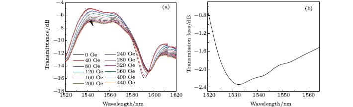 | Fig. 2. (a) Spectral response of the modulator to H. (b) Transmission losses at 1520– 1565 nm between 0 and 440 Oe. |
Figure 1(c) shows the schematic of the system for measuring the temporal response of the modulator. A tunable light source (TLS, AQ8640) is used to inject light into the modulator at a specific wavelength. The output light is converted into a voltage signal by a photodetector (Thorlabs Co.) and the results are recorded in a personal computer. Owing to the limitation to the output light range (1500– 1580 nm) of the TLS, we choose 1556.2 (a monotonic wavelength) and 1580 nm (a non-monotonic wavelength) as the modulated wavelength. From Fig. 2(a) the transmittance dependences on H at 1556.2 and 1580 nm can be obtained and shown in Figs. 3(a) and 3(c) respectively. Then by switching on/off the applied magnetic field of 600 Oe, the corresponding temporal responses of the modulator are recorded and shown in Figs. 3(b) and 3(d), respectively.
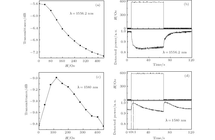 | Fig. 3. Transmittance dependences on H at (a) 1556.2 and (c) 1580 nm. The temporal responses of modulator when the modulated wavelengths are (b) 1556.2 and (d) 1580 nm, respectively. |
Firstly, by comparing Figs. 3(a) and 3(b) with Figs. 3(c) and 3(d), respectively, it can be seen that the response of the intensity of output light to time at a monotonic wavelength (1556.2 nm), where the transmittance changes monotonically with H, is also monotonic after the magnetic field has been switched on/off, while it is non-monotonic at a non-monotonic wavelength (1580 nm). First it increases at time t0 and reaches a maximum value at t1 then decreases to a stable value after the field has been switched on as shown in Fig. 3(d). Secondly, from Figs. 3(b) and 3(d) we can see that after the external magnetic field is switched on/off, it needs some time for the transmitted light intensity to reach a stable value. The two phenomena can be explained by the dynamic response process of the MF, i.e., the magnetic particles in the MF need to move and aggregate/disperse from an initial state to the final stable state after the applied magnetic field has been switched on/off.[3, 8, 22] Besides, the first phenomenon further indicates that the modulator can work well only at the monotonic wavelength, which is termed working wavelength by us here. Because the two wavelengths (1556.2 and 1580 nm) are not peculiar ones, the conclusions should be valid for any wavelength according to whether it is a monotonic one or a non-monotonic one.
It is worth noting that because the transmission spectrum is sensitive to the length of multimode waveguide section, [23] namely the length of the NCF in this paper, we can make the wavelength we want to modulate be located in the working wavelength range by adjusting the length of NCF finely.
3.2. Influence of H
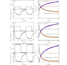
Once the modulator’ s working wavelength range is identified, we can investigate the temporal response of the modulator at a given suitable wavelength. It appears that, to be used as a modulator, the working wavelength should be a monotonic one. Meanwhile, the working wavelength should be close to the maximum of the transmittance change and should also have a low insertion loss. Therefore, 1534 nm is chosen based on Fig. 2. Figures 4(a), 4(c), and 4(e) show the temporal responses of the modulator when H is switched between 0 and 160, 320, and 600 Oe, respectively. The falling/rising relaxation processes fitting to an exponential function.[1]p = pf + pae– t/τ fall/p = pf − paet/τ rise are shown in Figs. 4(b), 4(d), and 4(f), where p is the normalized power of the output light; pf and pa are the fitting coefficients; t is the time; and τ fall/τ rise is the decay constant of the exponential function representing the rate of change of detected power with time. From Figs. 4(b), 4(d), and 4(f) we can see that the values of τ fall are 3.748, 2.575, and 1.961 s, and the values of τ rise are 5.479, 5.390, and 5.411 s, when the H is switched on/off between 0 and 160, 320, and 600 Oe, respectively. It can be found that τ fall decreases with the increase of H; however, H has no appreciable influence on τ rise.
 | Fig. 4. (a), (c), (e) Temporal response of modulator with the MF’ s concentration of 3.9% when the magnetic field is switched on/off between 0 and 160, 320, and 600 Oe, respectively; (b), (d), (f) the corresponding exponential functions fitting to the detected power depending on time. |
The results can be understood by the interaction between magnetic attraction and thermal agitation existing in MF.[1] The former makes the magnetic particles aggregate, while the latter makes the magnetic particles disperse. Following the increase of H, the magnetic energy will become larger and larger than the thermal energy, which will lead to a shorter time for magnetic particles to aggregate to the stable state after the magnetic field has been switched on. However, since the thermal agitation is the main reason for dispersing and the temperature is constant during the experiment, so τ rise almost does not change with H.
3.3. Influence of MF concentration
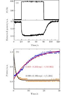
The dependence of the temporal response of the modulator on the density of the MF is also analyzed. We use the MF with a 1.95% concentration to replace the former MF with a 3.9% concentration. Firstly, the transmission spectral responses of the modulator to H are analyzed. It is found that the working wavelength is optimal at 1525 nm where the transmittance change is largest when H changes from 0 to 440 Oe. Figure 5 shows the temporal response of the modulator when the magnetic field is switched on/off between 0 and 600 Oe. Figure 5(b) indicates that τ fall and τ rise are 1.204 and 10.902 s respectively. Comparing with the 1.961 and 5.411 s obtained from Fig. 4(f), in which the magnetic field is switched on/off between 0 and 600 Oe as well, it can be found that as the concentration changes from 3.9% to 1.95%, τ fall decreases by about 0.76 s while τ rise increases about twice. These data indicate that a lower concentration is helpful to reduce τ fall but will significantly increase τ rise.
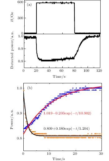 | Fig. 5. (a) Temporal response of device with an MF concentration of 1.95% when modulated between 0 and 600 Oe. (b) The corresponding exponential functions fitting. |
This phenomenon is due to the fact that a lower concentration is accompanied with a lower viscosity and a longer average distance among magnetic particles. Keeping the applied H unchanged, once the magnetic field is switched on, the lower viscosity will make it easier for magnetic particles to move and a shorter time (i.e., τ fall) is needed to aggregate to a stable state. However, when the magnetic field is switched off, the longer average distance among magnetic particles will lead to a longer time (i.e., τ rise) for magnetic particles to diffuse to the stable state by thermal agitation.
It is worth noting that the proposed modulator cannot be used for applications requiring a fast speed due to its slow response, though it possesses applications where speed is a secondary consideration. Furthermore, the response time has a great relationship with MF’ s properties (concentration etc.), so the suitable MF can be chosen for different applications.
4. Conclusions
In this paper, an all-fiber modulator based on MF and the SNS fiber structure is proposed and investigated with focusing on temporal response characteristics. The output light intensity is modulated by switching on/off an applied magnetic field, owing to the tunable refractive index and absorption coefficient of MF. First of all the wavelength dependence of the modulator is analyzed. It is found that there is a working wavelength range, in which the transmittance change is monotonic with H. It is also found that a stronger H or a lower concentration of MF can result in a shorter τ fall, and H has no significant influence on τ rise, but the MF with a lower concentration will lead to a longer τ rise. These results are explained qualitatively by the dynamic response of MF under the action of a magnetic field.
Reference
| 1 |
|
| 2 |
|
| 3 |
|
| 4 |
|
| 5 |
|
| 6 |
|
| 7 |
|
| 8 |
|
| 9 |
|
| 10 |
|
| 11 |
|
| 12 |
|
| 13 |
|
| 14 |
|
| 15 |
|
| 16 |
|
| 17 |
|
| 18 |
|
| 19 |
|
| 20 |
|
| 21 |
|
| 22 |
|
| 23 |
|