Wang Zhi-Yuan, Hou Chun-Ping. Crosstalk elimination in multi-view autostereoscopic display based on polarized lenticular lens array* . Chinese Physics B, 2015, 24(1): 014213
Permissions
Crosstalk elimination in multi-view autostereoscopic display based on polarized lenticular lens array*
Wang Zhi-Yuan†, Hou Chun-Ping
School of Electronic Information Engineering, Tianjin University, Tianjin 300072, China
Project supported by the National High Technology Research and Development Program of China (Grant No. 2012AA03A301), the National Natural Science Foundation of China (Grant No. 60932007), the Postdoctoral Science Programs Foundation of the Ministry of Education of China (Grant No. 0110032110029), and the Key Projects in the Tianjin Science & Technology Pillar Program, China (Grant No. 11ZCKFGX02000).
Abstract
An autostereoscopic display composed of a directional backlight, an image display panel, a striped half-wave plate, and a polarized lenticular lens array is proposed. The directional backlight emitting the parallel light can redirect the cones of light to lenticular lens array and reduce the chromatic spatial-interference effect. The striped half-wave plate, located in front of the image display panel, transformed the polarization direction of the lights from the directional backlight into two mutually perpendicular directions. The polarized lenticular lens array not only can divide the light from the left and right view images to send to left and right eyes but also can reduce the crosstalk of the stereoscopic images. The proposed autostereoscopic display can produce high quality stereoscopic images without crosstalk at the optimal viewing distance.
Autostereoscopic displays have attracted much attention due to creating the three-dimensional depth impressions without wearing any viewing aid.[1, 6] The major technologies for autostereoscopic displays are parallax barriers and lenticular lens arrays (LLAs), which are often attached in front of actual image display panels, such as the liquid crystal display (LCD) panel.[7, 14] Particularly, LLAs have been widely used in practice because LLAs provide higher brightness than parallax barriers in the autostereoscopic display.[15] The light from the left and right view images which is separated by the optical filters, such as a parallax barrier and an LLA, should only reach the left and right eyes in the autostereoscopic display, respectively. However, imperfect separation of the light from the left and right view images may be leaked to the right and left eyes, respectively. The leakage of light from one view image channel to another is a phenomenon known as crosstalk, which is often a critical and primary factor causing eye fatigue and degrading stereo image quality in an autostereoscopic display.[16]
In the LLA autostereoscopic displays, moiré pattern is induced by the optical components with regular structures, such as LCD panels and LLAs.[17] In order to reduce the moiré pattern, the most popular method is to assemble the lenticular lens at a certain inclined angle in the LLA autostereoscopic displays. Compared with the vertical LLA which only reduces resolution in the horizontal direction, the slanted LLA can not only minimize the moiré pattern but also balance the horizontal and vertical resolution. In the LLA autostereoscopic displays, the covered shape of the subpixels by the slanted lenticular lens element is parallelogram and the shape of the subpixels on the image display panel is rectangular. The difference between the parallelogram and rectangle brings about a consequence that the slanted LLA element cannot cover the boundaries of subpixels exactly. The lights from parts of subpixels pertaining to other views are leaked to the current view and cause considerable crosstalk.[13, 14, 16] Various methods have been proposed to reduce the crosstalk in the LLA autostereoscopic displays, such as two layer lenticular lenses through focusing the light by the additional one layer lenticular lens, correcting the intensity values of subpixels on synthetic images, and combining viewer tracking system and a synchro-signal LED scanning backlight module.[12, 14, 18] However the methods presented above only reduce the crosstalk to some degree, only compensate the observed image intensity for one view image rather than for all view images at the same time or require an extra tracking sensor.
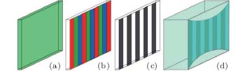
In this paper, we propose an autostereoscopic display that consists of a directional backlight, an image display panel, a striped half-wave plate, and a polarized lenticular lens array (PLLA), as schematically shown in Fig. 1. The proposed prototype eliminates the crosstalk by blocking the leakage of light from the parts of subpixels that belong to the other view image to the current view image. The ray tracing simulation shows that a high quality stereoscopic image without crosstalk is observed at the optimal viewing distance in the proposed multi-view autostereoscopic display.
Fig. 1. Structure of the proposed autostereoscopic display. (a) Directional backlight, (b) LCD, (c) striped half-wave plate, and (d) polarized lenticular lens array.
2. Structure and principle
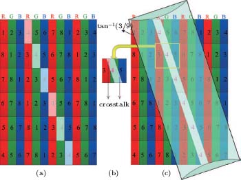
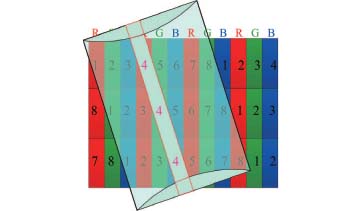
As shown in Fig. 2, a conventional LCD panel and slanted LLA with the angle tan− 1(3/9) are configured in an eight-view autostereoscopic display. In the LLA autostereoscopic display, for simplicity, only the subpixels with the rectangular shapes corresponding to the fourth view image illuminated with white color are prepared to display through the directly above lenticular lens on the synthetic image, as shown in Fig. 2. After attaching the slanted LLA, the observed subpixels’ shape through the LLA is parallelogram but not rectangular. The subpixels observed through the lenticular lens consist of the main parts of subpixels from the fourth view image and some parts of subpixels from the third and fifth view images as shown in Figs. 2(b) and 2(c). Therefore the light from the neighboring view images leads to the main crosstalk towards the observed image in the slanted LLA autostereoscopic display. Crosstalk can be defined by the following expression:[16]
where Ileakage is the intensity of light leaking in the wrong viewing zone and Isignal is the intensity of light in the right viewing zone.
Fig. 2. Distribution mode of the subpixels of each view image on the synthetic image. (a) The fourth view image prepared to display, (b) illustration of crosstalk and (c) the fourth view image observed through the LLA.
In the LLA autostereoscopic display, only a limited cone of lights is effectively utilized and the other lights cause crosstalk which increases with the increase of the view number.[19] Traditional backlight with Lambertian distribution is replaced by directional backlight to collimate light illumination, enhance efficiency of light utilization and improve the wide view zone and resolution in the autostereoscopic displays.[20, 21]
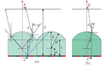
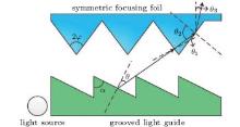
The directional backlight used in our proposed prototype is an improvement based on the directional backlight proposed by Chien.[20] The proposed directional backlight composed of a grooved light guide in combination with a symmetric focusing foil, as shown in Fig. 3. The vertex angle of grooved light guide and the half vertex angle of symmetric focusing foil are α and φ , respectively. To analyze the relationship between the light emitted from the grooved light guide with θ and the light emitted from the directional backlight with θ 3, the following relations can be obtained using the ray tracing method:[20]
where n1, θ 1, and θ 2 are the refractive index of the focusing foil, the refracted angle at the interface of grooves, and the incident angle at the interface of grooves, respectively. When the emitted angle of directional backlight θ 3 is zero, the direction of propagation of emitted light is parallel which is perpendicular to the LLA. In practice, a simple method for converging the light from the traditional backlight in parallel is to assemble a collimating lens in the front of the image display panel.[22] The profile of the collimating lens can be calculated by Lensmaker’ s formula.[23]
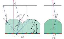
The intensity profile is simulated to analyze the influence on the intensity distribution using the directional backlight instead of the traditional backlight via the ray tracing method.[15, 19, 24] The light emitted with an angle ϕ from the position x will reach the viewing plane at position X after passing through the LLA, as shown in Fig. 4(a). The following equations can be obtained according to the geometric relationship:[19]
where
where R is the radius of lenticular sphere, d is the distance between the center and the image display panel, L is the viewing distance between the image display panel and the viewing plane, t is the gap between the lenticular lens and image display panel and n2 is the refractive index of LLA, as illustratively shown in Fig. 4. The intensity of light can be obtained by summing of all light rays from a subpixel
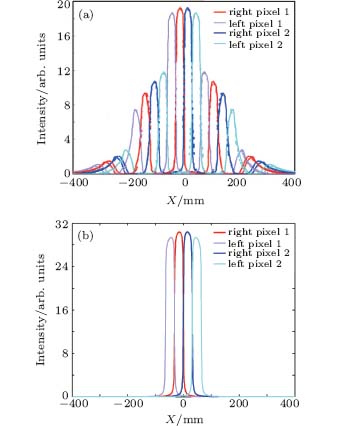
where xs is the starting position of the subpixel and w is the width of a subpixel. The backlight is the conventional backlight, , and cos ϕ denotes the Lambertian light source, ϕ 0 = − tan− 1((x + w)/h), ϕ M = tan− 1((w− x)/h). The backlight is the directional backlight, f(ϕ ) = 1. The light emitted with an angle ϕ from the position x only reaches the viewing position X, which contributes to the intensity of light in position X. Figure 5 shows the intensity distribution from subpixels in the right and left pixels on the viewing plane for a four view autostereoscopic display with a traditional backlight and a directional backlight, respectively. Compared with the intensity distribution with the traditional backlight as shown in Fig. 5(a), [19] the intensity distribution with a directional backlight contributed by the subpixel through the directly above lenticular lens coincides very well, and the intensity contributed by the combinations of subpixels through the adjacent lenticular lens is eliminated, as shown in Fig. 5(b).
Fig. 5. Simulated intensity distribution on the viewing plane for a four-view autostereoscopic display with (a) a traditional backlight[19] and (b) a directional backlight.
The primary differences between the traditional backlight and the directional backlight are the divergence angle. Figure 4 schematically shows the light propagation with a traditional backlight and a directional backlight. Light from subpixel with a traditional backlight emitting diverging light could pass through all parts of the lens directly above and the adjacent lens as shown in Fig. 4(a), which results in the unexpected spectral and spatial interferences, [19] However, light from subpixel with a directional backlight emitting parallel light could only pass through the upper parts of the lens directly above as shown in Fig. 4(b), which reduces the unexpected spectral and spatial interferences. Therefore, the parallel light from the observed pixel of the fourth view images only pass through the corresponding upper parts of the lens directly above (indicated by the red rectangles) when the LLA is assembled with a slanted angle, as shown in Fig. 6.
Fig. 6. Illustration of light from the observed pixel of the fourth view images with directional backlight only passing through the corresponding upper parts of the lens directly above (indicated by the red rectangles).
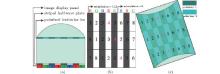
Figure 7 depicts the detailed structure and operation principle of the proposed autostereoscopic display. The similar operation principle has been used in polarized glasses-based stereoscopic displays.[3, 25] The striped half-wave plate acting as polarization switch was attached in front of the display panel. The polarized lenticular lens can be fabricated by attaching the patterned polarizer layer on the back side of the lenticular lens. The period length of the striped half-wave plate is equal to the subpixel pitch, where λ /2 optical retardation and zero optical retardation are adjacent to each other. The polarization direction of the image light from the image display panel is supposed to orient horizontally. The polarization direction of the incident image lights does not change and changes by 90° with respect to the initial direction after passing through the zero and λ /2 optical retardation, respectively.[26, 28] Therefore, the polarization direction of the incident image lights from the first row of subpixels corresponding to the view 2, view 4, view 6, and view 8 is still horizontal direction after passing through the striped half-wave plate because the optical retardation of the striped half-wave plate panel is zero, as shown in Fig. 7(b). Similarly, the polarization direction of the incident image lights from the first row of subpixels corresponding to the view 1, view 3, view 5, and view 7 becomes vertical direction after passing through the striped half-wave plate because the optical retardation of the striped half-wave plate panel is λ /2, as shown in Fig. 7(b).
Fig. 7. Detailed structure of the proposed autostereoscopic display. (a) Sectional view of the proposed autostereoscopic display, (b) scheme of the striped half-wave plate, and (c) scheme of the PLLA.
In this proposed autostereoscopic display, the backlight is transformed into two mutually perpendicular polarized lights after passing through the striped half-wave plate. After that, two polarized lights with horizontal and vertical direction pass through the corresponding polarizer units of each period of the PLLA. Every individual PLLA is composed of two isometric and mutually perpendicular polarizers, polarizer 1 with vertical direction and polarizer 2 with horizontal direction, as shown in Fig. 7(c). The lights with the horizontal polarization direction from the first row of subpixels for view 2, view 4, view 6, and view 8 can pass through the polarizer 1 of the PLLA because their transmission directions are the same and are blocked by polarizer 2 of the PLLA because their transmission directions are mutually perpendicular. Similarly, the lights with the vertical polarization direction from the first row of subpixels for view 1, view 3, view 5, and view 7 can pass through the polarizer 2 of the PLLA because their transmission directions are the same and are blocked by polarizer 1 of the PLLA because their transmission directions are mutually perpendicular.
3. Results and discussion
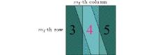
Figure 8 illustratively shows an enlarged light polarization direction and distribution of the m1-th row and m2-th column observed pixel on the synthetic image after passing through the striped half-wave plate when the viewer located in the range of the fourth view image along the optimal viewing distance. The observed pixel consists of the subpixel from the fourth view image and the subpixel from the third view image located at the top left corner of the observed pixel and the fifth view image located at the bottom right corner of the observed pixel. We assumed that the polarization direction of the light emitted from the fourth view image is the horizontal direction after passing through the striped half-wave plate. As can be seen from Fig. 7, the polarization direction of the light emitted from the third and fifth view images is vertical direction after passing through the striped half-wave plate. According to the definition of the crosstalk given in Eq. (1), the light emitted from the top left and bottom right corner of the observed pixel is the major source of crosstalk, because that light from the corner areas does not belong to the fourth view image. Therefore, blocking the light from the top left and bottom right corner of the pixel should help reducing crosstalk. The light from the subpixel of the fourth view image with horizontal direction is observed through the corresponding polarizer unit of the PLLA because the polarization direction of the corresponding polarizer unit of the PLLA is also vertical direction. However, the light from the subpixel of the third view image and the fifth view image is blocked because the polarization direction of the light is perpendicular to the polarization direction of the corresponding polarizer unit of the PLLA. This means that the crosstalk is eliminated when the light from top left and bottom right corner of the observed pixels is blocked.
Fig. 8. Illustration of light polarization direction and distribution of the observed pixel in the m1-th row and m2-th column pixel.
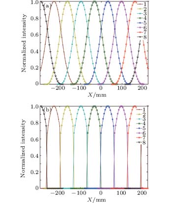
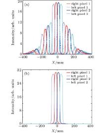
The normalized intensity distribution of the eight view images along the horizontal direction at the optimal viewing distance in the conventional LLA autostereoscopic display by simulation using ray tracing method is schematically shown in Fig. 9(a).[15] The normalized intensity distribution calculated using ray tracing method coincides very well with that from experiment measurement.[13] When the viewer located in the range of the fourth view image along the optimal viewing distance, the viewer observed the stereoscopic image with crosstalk which results from the third and fifth view images because the viewing zones overlap, as shown in Fig. 9(a). According to the definition of the crosstalk in Eq. (1), the minimum crosstalk is about 0.33 in the conventional LLA autostereoscopic display. However, it can be seen from Fig. 9(b) that the viewing zones do not overlap in the proposed autostereoscopic display. The crosstalk is very close to zero in the PLLA autostereoscopic display. Compared with the other methods for reducing crosstalk, [12, 14, 18] the proposed method is simple and effective. Moreover, it does not change the parameters of the lenticular lens, process the view image and need auxiliary viewer tracking system. The viewer will observe the high quality stereoscopic image without crosstalk when the viewer is located in the range of the fourth view image along the optimal viewing distance, because the light from the third and fifth view images causing crosstalk were blocked by the corresponding polarizer units of the PLLA. Thus, the crosstalk of the obsearved view images caused by the neighbouring view images is eliminated in the proposed multi-view autostereoscopic display.
Fig. 9. Normalized intensity distribution on the viewing plane for an eight view autostereoscopic display based on (a) lenticular lens array and (b) polarized lenticular lens array.
4. Conclusion
The multi-view autostereoscopic display based on a polarized lenticular lens array with a directional backlight and a striped half-wave plate was proposed. To concentrate the light emitted from the image panel, the directional backlight is adopted to replace the traditional backlight. The polarization of the light emitted from the directional backlight is transformed into two mutually perpendicular directions after passing through the striped half-wave plate located onto the front of image display panel. The polarized lenticular lens array can not only separate the left and right image light to create the three-dimensional perception of image but also block specific polarization direction of lights. The operation principle of proposed prototype to reduce crosstalk is that the light with the same transmission direction as the PLLA can pass through the PLLA and with the perpendicular transmission direction as the PLLA is completely blocked by the PLLA. The simulation results indicate that the crosstalk is eliminated in the proposed autostereoscopic display. As a result, the viewer will observe high quality stereoscopic images without crosstalk at the optimal viewing distance.
WangP S, YaoJ M, LinZ X, XuS and GuoT L2011J. Optoelectron. Laser22827(in Chinese)[Cited within:1][CJCR: 1.454]
8
TangX Z, ChungT C, JenT H, LuJ G and ShiehH P2013Acta Phys. Sin. 62164212(in Chinese)DOI:10.7498/aps.62.164212[Cited within:1][JCR: 1.016][CJCR: 1.691]
GradyN K, HeyesJ E, ChowdhuryD R, ZengY, ReitenM T, AzadA K, TaylorA J, DalvitD A R and ChenH T2013Science3401304DOI:10.1126/science.1235399[Cited within:1]
... [1,6] The major technologies for autostereoscopic displays are parallax barriers and lenticular lens arrays (LLAs), which are often attached in front of actual image display panels, such as the liquid crystal display (LCD) panel ...
1
2005
1.675
0.0
1
2011
1.689
0.0
... [3,25] The striped half-wave plate acting as polarization switch was attached in front of the display panel ...
... [1,6] The major technologies for autostereoscopic displays are parallax barriers and lenticular lens arrays (LLAs), which are often attached in front of actual image display panels, such as the liquid crystal display (LCD) panel ...
1
2011
0.0
1.454
... [7,14] Particularly, LLAs have been widely used in practice because LLAs provide higher brightness than parallax barriers in the autostereoscopic display ...
1
2013
1.016
1.691
1
2008
0.0
0.0
1
2009
0.88
0.0
1
2006
0.88
0.0
2
2010
3.385
0.0
... [12,14,18] However the methods presented above only reduce the crosstalk to some degree, only compensate the observed image intensity for one view image rather than for all view images at the same time or require an extra tracking sensor ...
... Compared with the other methods for reducing crosstalk,[12,14,18] the proposed method is simple and effective ...
2
2011
0.968
0.9021
... [13,14,16] Various methods have been proposed to reduce the crosstalk in the LLA autostereoscopic displays, such as two layer lenticular lenses through focusing the light by the additional one layer lenticular lens, correcting the intensity values of subpixels on synthetic images, and combining viewer tracking system and a synchro-signal LED scanning backlight module ...
... [13] When the viewer located in the range of the fourth view image along the optimal viewing distance, the viewer observed the stereoscopic image with crosstalk which results from the third and fifth view images because the viewing zones overlap, as shown in Fig ...
4
2011
1.663
0.0
... [7,14] Particularly, LLAs have been widely used in practice because LLAs provide higher brightness than parallax barriers in the autostereoscopic display ...
... [13,14,16] Various methods have been proposed to reduce the crosstalk in the LLA autostereoscopic displays, such as two layer lenticular lenses through focusing the light by the additional one layer lenticular lens, correcting the intensity values of subpixels on synthetic images, and combining viewer tracking system and a synchro-signal LED scanning backlight module ...
... [12,14,18] However the methods presented above only reduce the crosstalk to some degree, only compensate the observed image intensity for one view image rather than for all view images at the same time or require an extra tracking sensor ...
... Compared with the other methods for reducing crosstalk,[12,14,18] the proposed method is simple and effective ...
In this paper, we developed an optical model describing the behavior of light at the surface of a slanted lenticular array for autostereoscopic displays in three dimensions and simulated the optical characteristics of autostereoscopic displays using the Monte Carlo method under actual design conditions. The behavior of light is analyzed by light rays for selected inclination and azimuthal angles; numerical aberrations and conditions of total internal reflection for the lenticular array were found. The intensity and the three-dimensional crosstalk distributions calculated from our model coincide very well with those from conventional design software, and our model shows highly enhanced calculation speed that is 67 times faster than that of the conventional software. From the results, we think that the optical model is very useful for predicting the optical characteristics of autostereoscopic displays with enhanced calculation speed. (C) 2013 Optical Society of America
Jung, Sung-Min 1 ;Kang, In-Byeong 1 ;
... [15] The light from the left and right view images which is separated by the optical filters, such as a parallax barrier and an LLA, should only reach the left and right eyes in the autostereoscopic display, respectively ...
... [15,19,24] The light emitted with an angle #cod#x03D5 ...
... [15] The normalized intensity distribution calculated using ray tracing method coincides very well with that from experiment measurement ...
3
2012
1.061
0.0
... [16] ...
... [13,14,16] Various methods have been proposed to reduce the crosstalk in the LLA autostereoscopic displays, such as two layer lenticular lenses through focusing the light by the additional one layer lenticular lens, correcting the intensity values of subpixels on synthetic images, and combining viewer tracking system and a synchro-signal LED scanning backlight module ...
... Crosstalk can be defined by the following expression:[16](1)
1
2005
1.663
0.0
... [17] In order to reduce the moir#cod#x00E9 ...
2
2011
1.663
0.0
... [12,14,18] However the methods presented above only reduce the crosstalk to some degree, only compensate the observed image intensity for one view image rather than for all view images at the same time or require an extra tracking sensor ...
... Compared with the other methods for reducing crosstalk,[12,14,18] the proposed method is simple and effective ...
5
2013
1.689
0.0
... [19] Traditional backlight with Lambertian distribution is replaced by directional backlight to collimate light illumination, enhance efficiency of light utilization and improve the wide view zone and resolution in the autostereoscopic displays ...
... [15,19,24] The light emitted with an angle #cod#x03D5 ...
... The following equations can be obtained according to the geometric relationship:[19](5)
... 5(a),[19] the intensity distribution with a directional backlight contributed by the subpixel through the directly above lenticular lens coincides very well, and the intensity contributed by the combinations of subpixels through the adjacent lenticular lens is eliminated, as shown in Fig ...
... 4(a), which results in the unexpected spectral and spatial interferences,[19] However, light from subpixel with a directional backlight emitting parallel light could only pass through the upper parts of the lens directly above as shown in Fig ...
3
2006
1.689
0.0
... [20,21] ...
... [20] The proposed directional backlight composed of a grooved light guide in combination with a symmetric focusing foil, as shown in Fig ...
... 3, the following relations can be obtained using the ray tracing method:[20](2)
Multiview three-dimensional (3D) displays can project the correct perspectives of a 3D image in many spatial directions simultaneously(1-4). They provide a 3D stereoscopic experience to many viewers at the same time with full motion parallax and do not require special glasses or eye tracking. None of the leading multiview 3D solutions is particularly well suited to mobile devices (watches, mobile phones or tablets), which require the combination of a thin, portable form factor, a high spatial resolution and a wide full-parallax view zone (for short viewing distance from potentially steep angles). Here we introduce a multi-directional diffractive backlight technology that permits the rendering of high-resolution, full-parallax 3D images in a very wide view zone (up to 180 degrees in principle) at an observation distance of up to a metre. The key to our design is a guided-wave illumination technique based on light-emitting diodes that produces wide-angle multiview images in colour from a thin planar transparent light-guide. Pixels associated with different views or colours are spatially multiplexed and can be independently addressed and modulated at video rate using an external shutter plane. To illustrate the capabilities of this technology, we use simple ink masks or a high-resolution commercial liquid-crystal display unit to demonstrate passive and active (30 frames per second) modulation of a 64-view backlight, producing 3D images with a spatial resolution of 88 pixels per inch and full-motion parallax in an unprecedented view zone of 90 degrees. We also present several transparent hand-held prototypes showing animated sequences of up to six different 200-view images at a resolution of 127 pixels per inch.
Fattal, David 1 ;Peng, Zhen 1 ;Tho Tran 1 ;Vo, Sonny 1 ;Fiorentino, Marco 1 ;Brug, Jim 1 ;Beausoleil, Raymond G. 1 ;
... [20,21] ...
1
2010
1.101
0.0
... [22] The profile of the collimating lens can be calculated by Lensmaker#cod#x2019 ...
In this study, we suggest a customized model describing optical phenomena at the surface of a lenticular array for autostereoscopic displays in a mathematical form and analyzed the optical characteristics of lenticular array for the first time. We checked the validity of our mathematical model by examining and comparing our result with conventional lens theory. Monte Carlo simulations were performed to obtain the angular distribution of light from each sub-pixel corresponding to each views under actual design conditions. From the results, we think the optical model is very useful for designing optical parameters of autostereoscopic displays. (C) 2013 Elsevier B. V. All rights reserved.
... [15,19,24] The light emitted with an angle #cod#x03D5 ...
1
2009
0.0
0.0
... [3,25] The striped half-wave plate acting as polarization switch was attached in front of the display panel ...
1
2010
3.385
0.0
... [26,28] Therefore, the polarization direction of the incident image lights from the first row of subpixels corresponding to the view 2, view 4, view 6, and view 8 is still horizontal direction after passing through the striped half-wave plate because the optical retardation of the striped half-wave plate panel is zero, as shown in Fig ...
Filamentary discharges in dielectric barrier discharge operating in a glow regime are studied by use of two-dimensional particle-in-cell simulation with Monte Carlo collisions included. The formation of multiple filaments and the involved electric fields, electric potentials, plasma densities, and particle temperatures are presented. It is found that the filaments are not ignited simultaneously, and they expire with the shift of the plasma sheaths. "Dark discharges", which produce ion densities lower by one order of magnitude than a typical filamentary discharge, are observed while the filaments from earlier discharges are decaying. (C) 2013 American Institute of Physics. [http://dx.doi.org/10.1063/1.4794824]
... [26,28] Therefore, the polarization direction of the incident image lights from the first row of subpixels corresponding to the view 2, view 4, view 6, and view 8 is still horizontal direction after passing through the striped half-wave plate because the optical retardation of the striped half-wave plate panel is zero, as shown in Fig ...
Crosstalk elimination in multi-view autostereoscopic display based on polarized lenticular lens array*


