
Fluctuations of optical phase of diffracted light for Raman–Nath diffraction in acousto–optic effect*
Cite this Article
Weng Cun-Cheng, Zhang Xiao-Man. Fluctuations of optical phase of diffracted light for Raman–Nath diffraction in acousto–optic effect* . Chinese Physics B, 2015, 24(1): 014210 
Permissions
Fluctuations of optical phase of diffracted light for Raman–Nath diffraction in acousto–optic effect*
Corresponding author. E-mail: xmzhang@fjnu.edu.cn
Project supported by the National Natural Science Foundation of China (Grant No. 61178089) and the Science and Technology Program of the Educational Office of Fujian Province of China (Grant Nos. JB12012 and JB13003).
Abstract
The Raman–Nath diffraction in acousto–optic effect was studied theoretically and experimentally in the paper. Up to now, each order of diffracted light in Raman–Nath diffraction was still considered simply to be just frequency-shifted and to be a plane wave. However, we find that the phase and frequency shifts occur simultaneously and individually in Raman–Nath diffraction. The findings demonstrate that, in addition to the frequency shift, the optical phase of each order of diffracted light is also shifted by the sound wave and fluctuates with the sound wave and is related to the location in the acoustic field from which the diffracted light originates. As a result, the wavefront of each order of diffracted light is modulated to fluctuate spatially and temporally with the sound wave. Obviously, these findings are significant for applications of Raman–Nath diffraction in acousto–optic effect because the optical phase plays an important role in optical coherence technology.
Keyword:
42.65.–k; 43.35.+d; 42.25.Fx; Raman–Nath diffraction; acousto–optic effect; phase shift; frequency shift
1. Introduction
Acousto– optic effects occur in all optical media. So far, acousto– optic effects have been applied to a wide range of optical system applications.[1, 5] When an acoustic wave is launched into an optical medium, it generates a phase grating. The incident light on the grating is diffracted.[6] The diffraction is divided into two distinct diffraction types: Raman– Nath and Bragg diffraction.[6] When the Klein– Cook parameter is less than 1, only the Raman– Nath diffraction occurs.[6] The Klein– Cook parameter Q obeys 
The Raman– Nath diffraction includes multiple diffraction orders. Each order of diffracted light has a specific frequency shift and a diffraction angle. However, each order of diffracted light was still considered as a plane light wave. In this paper, we find that each order of diffracted light is not a plane light wave, and that its optical phase is shifted by the sound wave and fluctuates with the sound wave and is the function of the location inside the acoustic field from which the diffracted light originates. As a result, the wavefront of each order of diffracted light is modulated to fluctuate spatially and temporally with the sound wave.
2. Theory
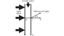
The sound– light interaction configuration we deal with is two dimensional, with the longitudinal sound wave propagating in the Y direction and the light wave in the Z direction. A typical configuration is seen in Fig. 1. This shows an idealized sound beam, being contained between planes z = 0 and z = l inside a medium. The medium is optically transparent. A plane light wave, of angular frequency ω 0, is incident from the left normal to the sound beam, θ is the deflection angle of the incident light.
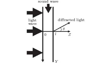 | Fig. 1. Sound– light interaction configuration. |
Consider an acoustic plane wave traveling in the medium with velocity v and angular frequency ω . The refractive index n(t, y) at position y and time t is[7, 9]
 |
where n0 is the refractive index of the medium in the absence of sound and m is the modulation constant of the refractive index. From Eq. (1), we can know that the refractive index of the medium in the acoustic field is modulated spatially and temporally by the sound wave.
2.1. A plane wave for each order of diffracted light in Raman– Nath diffraction
A light wave getting into the acoustic field will be diffracted. For Raman– Nath diffraction, the diffracted light E(t) was still expressed as[10, 11]
 |
where E0 is the electric field of incident light, k, ω 0, and λ are the wave vector, angular frequency, and the wavelength of incident light in vacuum, respectively, q is an integer, Jq denotes the qth-order Bessel function, and λ u is the acoustic wavelength in the medium.
It is seen from Eq. (2) that the qth-order of diffracted light is shifted in frequency by qω and its diffraction angle θ q obeys
 |
and each order of diffracted light has the same optical phase exp(jkn0l) and is a plane light wave. Additionally, the optical phase of each order of diffracted light is not shifted by the sound wave and does not fluctuate with the sound wave and is not related to the location y.
To reveal the relationship between the sound-modulated light and its origin (a specific location inside the acoustic field from which the modulated light originates), only the light escaping from a very small defined region inside the acoustic field is collected. The region is assumed a rectangle with the 2a and 2d sizes along the X- and Y-axes respectively. The regional center is a point (0, y, 0). Additionally, the regional sizes are much shorter than the acoustic wavelength in the medium. Then, all collected light can be considered to originate from the same location (0, y, 0) inside the acoustic field.
Generally, the diffracted light with the absolute diffraction order more than five is very weak.[12] Consequently, we can assume that only the diffracted light of the absolute diffraction order less than five is collected. Then, the collected light intensity I(t) is
 |
in which F(t) is a periodic function with acoustic period 2π /ω and obeys
 |
where Mq is a constant.
From Eqs. (4) and (5), the collected light intensity fluctuates with the sound wave but is not related to its origin y inside the acoustic field. Additionally, even though the values of a and d are increased, the collected light intensity is not also related to its origin y. In other words, the intensity is not also related to the origin y even though one or many orders of diffracted light, escaping from outside the small defined region, is also collected.
Additionally, if only the qth-order of diffracted light is collected, the collected light intensity will be
 |
From Eq. (6), the collected light intensity does not fluctuate with the sound wave and is not related to the origin y.
From above all, if each order of diffracted light for Raman– Nath diffraction is a plane light wave, the collected light intensity will not be related to the origin y even though one or many orders of diffracted light, escaping from outside the small defined region, is also collected. Additionally, the optical diffraction, caused by the small defined region, can be ignored in the derivation process.
2.2. Not a plane wave for each order of diffracted light in Raman– Nath diffraction
However, we believe that the spatial and temporal modulations of the refractive index, induced by the sound wave, will inevitably lead to the spatial and temporal fluctuations of the optical phase of diffracted light for Raman– Nath diffraction in acousto– optic effect. Consequently, the optical phase of each order of diffracted light must be shifted by the sound wave and fluctuate with the sound wave and be related to its origin y inside the acoustic field. In other words, equation (2) must be rewritten as
 |
where lqy is defined as the effective transmission distance of light in the acoustic field and is a function of q and y. If the qth-order diffracted light can be approximated to travel along the Z direction, the value of lqy will be able to be proximately equal to l. Here, both the frequency shift and diffraction angle of each order of diffracted light remain unchanged.
Firstly, only the zero-order diffracted light is collected. When the light passes through the acoustic field along the Z direction, only its optical phase is shifted by the sound wave. Then, the collected light intensity I(t, y) is
 |
It is very obvious that the value of (v/qω ) decreases rapidly with the absolute value of q. Consequently, the value of (v/qω )Jq(kn0lmn)sin(qω d/v) can be approximately zero for the absolute value of q more than five. Additionally, the value of d is much lower than the acoustic wavelength in the medium. In this case, equation (8) can be approximated as
 |
From Eq. (9), the collected light intensity fluctuates with the sound wave. Additionally, the intensity also fluctuates with its origin y over a cycle of acoustic wavelength in the medium and therefore the acoustic velocity can be obtained by a dual-trace phase measurement.
Secondly, for convenience of derivation, only the qth-order diffracted light, which can be approximated to travel along the Z direction, is collected. Then, the following equation derived similarly to the one for Eq. (9):
 |

From Eq. (10), the collected light intensity also fluctuates with the sound wave and its origin y.
In fact, because of optical diffraction, it is impossible that only the light escaping from the very small defined region is collected. According to Eqs. (8) and (10), for only collecting one order of diffracted light, the collected light intensity also fluctuates with the sound wave and its origin y even though the order of diffracted light, coming from outside the small defined region, is also collected. Consequently, here the optical diffraction can also be ignored in the derivation process.
3. Analysis
If each order of diffracted light for Raman– Nath diffraction in acousto– optic effect is a plane light wave, the collected light intensity will not fluctuate with the sound wave and its origin y inside the acoustic field for only collecting one order of diffracted light. Additionally, the collected light intensity will also not be related to the origin y even though many orders of diffracted light, escaping from outside the small defined region, is also collected.
However, if each order of diffracted light is not a plane light wave and its optical phase is shifted spatially and temporally by the sound wave, the collected light intensity will fluctuate with the sound wave and its origin y for only collecting one order of diffracted light.
Additionally, optical diffraction does not affect the above theoretical results.
4. Experiment
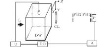
The experimental setup is shown in Fig. 2. A function generator output is a sine electrical signal that excites an unfocusing transducer to generate a continuous ultrasound with 1.0-MHz frequency and 10-mm diameter and about 104-Pa peak ultrasonic pressures in distilled water. The electrical signal is read by a dual trace oscilloscope. The distances from the central axis of the ultrasound beam to the front and left surfaces of a tank are approximately 3.5 cm and 2.5 cm, respectively. The tank, of which the dimensions are 7.0 cm× 9.0 cm× 5.0 cm along the X, Y, Z-axes respectively, holds 270-ml distilled water. He– Ne laser light, expanded to 3.0 cm in diameter after passing through a rectangular hole, is irradiated onto the tank along the Z direction. A convex lens, with the aperture of 25 mm and the focal length of 550 mm, is used. After the light, escaping from the tank, passing through the lens, a diffraction pattern in the lens focal plane is obtained by a CCD and is shown in Fig. 3. The distances from the lens optical center to the right surface of the tank and the pinhole 2 are approximately 50 mm and 550 mm, respectively. The distance between the two pinholes with the aperture of 0.2 mm is about 1.000 m. The line of the two pinholes’ centers and the lens optical center is parallel to the Z axis. The distance from pinhole 1 to PMT is about 1.0 cm. Optical signals are collected by a photo-multiplier tube (PMT) with the 4.0-mm incidence window in diameter, from which the electrical signals are also read by the oscilloscope after amplification by an amplifier. The two pinholes and PMT and convex lens are fixed together and can be moved together in the Y direction. An acoustic absorber is placed in the bottom of the tank.
 | Fig. 2. Schematic diagram of experimental setup. U: ultrasonic transducer and its driver; DO: digital oscilloscope; A: amplifier; P: photomultiplier; PH: pinhole; DW: distilled water; L: laser light; CL: convex lens. |
By calculation, the value of Q is about 0.014. Consequently, in the following experiments, the optical diffraction caused by the sound wave must be the Raman– Nath diffraction.
In this experiment, by spatial filtering effect of the convex lens and pinhole 2, it is possible for only one order of diffracted light to be collected. Additionally, pinhole 1 is used so that most of the collected light can be considered to originate from the specific location inside the ultrasonic field. Then, according to the above theoretical analysis, the optical diffraction of pinhole 1 can be ignored. At last, the electrical signals exciting the ultrasonic transducer are chosen as a reference, and then the fluctuation of optical signals from PMT with its origin y inside the acoustic field is observed and measured by a dual-trace phase measurement method.
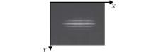
From Fig. 3, the diffraction pattern is regular and symmetrical, and the diffraction fringes are linear and parallel. Consequently, both the light diffraction along the X direction and the ultrasound diffraction can be ignored, and the ultrasound wave can be considered as a plane wave and the different order diffracted light can be separated. Additionally, the optical diffraction in the experiment must be the Raman– Nath diffraction since there are five diffraction fringes.
By calculation from Eq. (2), the diffraction angle of the first-order diffracted light is about 1.1 min and therefore the order of diffracted light can be approximated to travel along the Z direction. On the basis of the focal length of the lens and the aperture of pinhole 2, only the light with a diffraction angle smaller than 0.63 min can be collected. Additionally, by measuring the diffraction pattern (Fig. 3), the separation of diffraction stripes is three times more than the zero-order fringe width. Consequently, only the zero-order diffracted light can be collected in the experiment.
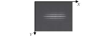 | Fig. 3. Diffraction pattern of Raman– Nath diffraction in the lens focal plane. |
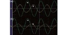
As shown in Fig. 4, when the two pinholes and PMT and convex lens are moved together in the Y direction, the waveform of the collected optical signals also moves and the waveform of the electrical signals remains still and the peaks of the two waveforms overlap periodically. Obviously, the relative movement has nothing to do with time and depends on the origin y. By the dual-trace phase measurement, the moving distance is about 1.46± 0.03 mm for a period. Then, the ultrasonic velocity in the distilled water is about 1.46× 10³ m/s, which is identical to the actual value. The experimental results show that the collected light intensity fluctuates with the sound wave and its origin y inside the acoustic field.
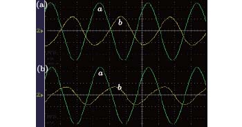 | Fig. 4. Two signal waveforms for two different detection positions from an oscilloscope. Curve a: electrical signals exciting the ultrasonic transducer. Curve b: ultrasound-modulated optical signals from PMT. (a) Position 1; (b) position 2. |
Secondly, only the two pinholes and PMT are moved together 0.176 mm in the Y direction so that only the first-order diffracted light is collected. Then, the above experiment is repeated. The experiment also shows that the collected light intensity fluctuates with the sound wave and its origin y.
Additionally, according to Eq. (4), if each order diffracted light for Raman– Nath diffraction in acousto– optic effect is a plane light wave, the collected light intensity will not be related to the origin y even though many orders of diffracted light, escaping from outside the small defined region, is also collected.
Consequently, each order of diffracted light for Raman– Nath diffraction in acousto– optic effect is not a plane light wave. Additionally, because of the spatial and temporal modulations of the refractive index, the optical phase of each order of diffracted light is shifted and fluctuates with the sound wave and is related to its origin inside the acoustic field.
5. Conclusions
We present the further theoretical and experimental studies on Raman– Nath diffraction in acousto– optic effect. The Raman– Nath diffraction includes multiple diffraction orders. Each order of diffracted light has a specific frequency shift and a diffraction angle. However, we found that each order of diffracted light is not a plane light wave. Additionally, the optical phase of each order of diffracted light is shifted by the sound wave and fluctuates with the sound wave and is the function of the location inside the acoustic field from which the diffracted light originates. As a result, the wavefront of each order of diffracted light is modulated to fluctuate spatially and temporally with the sound wave. Obviously, our findings are expected to be helpful for applications of Raman– Nath diffraction in acousto– optic effect.
Reference
| 1 |
|
| 2 |
|
| 3 |
|
| 4 |
|
| 5 |
|
| 6 |
|
| 7 |
|
| 8 |
|
| 9 |
|
| 10 |
|
| 11 |
|
| 12 |
|