Project supported by the National Natural Science Foundation of China (Grants Nos. 61331005, 11204378, 11274389, 11304393, and 61302023) and the National Natural Science Foundation of Shaanxi Province, China (Grant Nos. 2011JQ8031 and 2013JM6005).
Abstract
In this paper, we show that circular polarization-keeping reflection can be achieved using reflective metasurfaces. The underlying physical mechanism of the polarization-keeping reflection is analyzed using a reflection matrix. A wideband circular polarization-keeping reflector is demonstrated using N-shaped resonators. Both the simulation and experiment results show that the polarization-keeping reflection can be achieved with a high efficiency larger than 98% over the frequency range from 9.2 GHz to 17.7 GHz for both incident left- and right-handed circularly polarized waves. Under oblique incidence, the bandwidth increases as the incident angle varies from 0° to 80°. Moreover, the co-polarization reflection is independent of the incident azimuth angles.
Before 2011, meta-surfaces were considered as two-dimensional versions of metamaterials or frequency selective surfaces, which are composed of planar arrays of identical metallic patterns. Correspondingly, the research on metasurfaces focused mainly on their transmission/reflection performances. In the last two years, the concept of metasurface has been generalized to planar assembly of inhomogeneous metamaterial unit cells.[1– 5] It is considered as a single surface with a negligible sub-wavelength thickness, rather than frequency selective surfaces. Using metasurfaces, almost all the basic properties of EM waves can be tailored, including amplitude, phase, polarization and propagation modes, etc. Many studies on applications of metasurfaces have been implemented with distinct advantages over conventional methods, such as planar antennas, reflectarrays, [6] phase gradient metasurface, [7, 8] and polarization converter.[9– 19] Conventional polarization manipulation at microwave frequencies is always realized using chiral materials or multilayered metallic structures and suffers from the bulky volumes, high losses, and narrow bandwidth.[20– 25] In this regard, metasurfaces were proposed to implement polarization control. Light polarization manipulation with an ultra-thin plasmonic metasurface using orthogonal elongated nanorods and complementary nanoslits arrays was analyzed based on a simple impedance model to describe the array interaction.[10] A light polarization converter using a silver film with array of perforated S-shaped holes was realized to freely modulate the polarization angle.[11] Grady et al. demonstrated an ultra-thin, broadband, and highly-efficient polarization converter that is capable of rotating a linear polarization state into its orthogonal one.[1] The polarization selectivity and convertibility were simultaneously achieved by integrating the asymmetric split-ring resonators with the S-shape resonators in Ref. [12]. A broadband circular polarization converter using gold helix structures at optical frequencies was demonstrated in Ref. [13]. In microwave frequency range, a transmissive metasurface used to convert the linearly polarized signal from a source antenna into a circularly polarized signal is proposed and achieved.[14] In general, there are few papers on circular polarization (CP) conversion, compared with the linear polarization (LP) conversion and linear-to-circular polarization conversion. In particular, for a circularly polarized wave incident on conventional reflective mirrors such as metal plates, cross-polarization reflection always occurs. That is to say, after reflection, left-handed circularly polarized waves are converted into right-handed circularly polarized waves, and vice versa.
In this paper, we demonstrate that circular polarization-keeping reflection can be achieved using reflective metasurfaces. The metasurface is composed of N-shaped metallic pattern array backed with a metal ground. The working mechanism is analyzed using the reflection matrix. Because of the anisotropy of this structure in the two in-plane directions, the polarization state of reflected waves under left-handed circular polarization (LCP) waves and right-handed circular polarization (RCP) wave incidence can be kept with the co-polarization reflection larger than 98% over a wideband from 9.2 to 17.7 GHz. Under oblique incidences, the co-polarization reflection stays over 95% and is independent of the incident azimuth angles. The calculated axial ratio of reflected waves is less than 3 dB. Experimental results have good consistency with the simulated results.
2. Design of the reflective metasurface
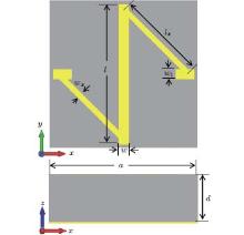
Figure 1 shows the unit cell of the metasurface, where the upper panel gives the front view and the lower panel gives the side view. The unit cell of the metasurface is composed of an N-shaped metallic pattern backed with a ground sheet. The N-shaped pattern and the ground sheet are separated by a dielectric spacer. The metal ground sheet makes the CP-keeping reflective metasurface reflect the whole incident wave, and the reverse of the propagation direction for the reflected wave can convert the polarization of the CP wave. The high-efficiency co-polarization reflection under CP wave incidence results from the resonances of the resonator composed by the N-shaped metallic wire and the copper ground sheet. The wide operating bandwidth is produced by the superposition of the three resonances. By delicate parameter sweep process, the optimized dimensions are determined as: a = 5.2 mm, d = 3 mm, w = 0.3527 mm, wx = 0.2 mm, w1 = 0.36 mm, l = 5 mm, lx = 3.4527 mm, t = 0.017, ly = 0.65. The dielectric spacer is with the permittivity ε = 2.65 and loss tangent tanδ = 0.001.
Fig. 1. Schematic view of the unit cell of the polarization converter and the corresponding geometrical parameters.
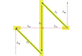
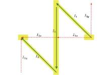
To analyze the mechanism of co-polarization reflection for LCP wave incidence, we decompose the incident CP waves into two linear polarized (LP) waves in x and y directions. Correspondingly, the incident electric field vector Ei is decomposed into two components in x and y directions perpendicular to the propagation direction. For a given point in space, the electric field components have the form , Eiy = ŷ Eeiπ /2. When these LCP waves illuminate on the metasurface as shown in Fig. 2, a resonance is produced in the N-shaped metallic structure with the action of the incident electric field. The induced current is described in the green arrowed line, and we have I1 = I2 = I3. Decomposing the currents I1 and I3 into x and y components is described in the red arrowed dashed line. In y direction, the current I2 can be considered as counter-balance y components of I1 and I3. Thus, the total net current is in the x direction. This N-shaped metal wire can be considered as an electric dipole in x direction. This tailors the phases of the scattering electric field in x and y directions and results in different phase changes in the two directions. Due to the different phase shifts in x and y directions, the polarization of the scattering fields is converted. For this reason, the polarization of the reflected wave is in keeping with the incidence wave because of the simultaneously inversed polarization state and propagation direction and the polarization of the transmitted wave is converted. The transmitted wave is reflected by the metal backsheet and the polarization is converted again. The highly efficient co-polarization reflection can be achieved through the multi-reflection in the Fabry– Perot like cavity resonator composed of the N-shaped metal pattern and the metal backsheet.
Fig. 2. Schematic diagram for the induced surface current on the N-shaped metallic structure at resonant frequencies.
3. Simulations and analysis
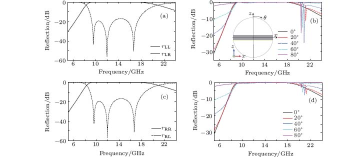
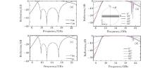
To verify the above design, we perform full-wave numerical simulations using CST Microwave Studio in 5.0– 24.0 GHz. The boundary conditions are unit cell in x and y directions and the input is the circularly polarized wave. The calculated co-polarization reflection and cross-polarization reflection are given in Figs. 3(a) and 3(c). In addition, the co-polarization reflections under oblique incidence are also considered in Figs. 3(b) and 3(d). The inset in Fig. 3(b) is given to describe the incident angle, where rLR(rRL) denotes the amplitude of the cross-polarization reflection coefficient under LCP (RCP) wave incidence and rLL (rRR) is the amplitude of co-polarization reflection coefficient under LCP (RCP) wave incidence. From Fig. 3, we can find that rLL and rRR have the same magnitude under normal incidence. Over a wide frequency band from 9.2 GHz to 17.7 GHz, the co-polarized reflected wave carries more than 98% of the incident energy, and the cross-polarized component carries below 2%. These results indicate that this metasurface is a wide-band and highly efficient CP mirror over a wide incident angle range from 0° to 80° .
Fig. 3. Simulated co-polarization and cross-polarization versus frequency under CP wave incidence, (a) co- and cross-polarization reflection under LCP wave incidence, (b) co-polarization reflection under LCP waves incident with different incident angles, (c) co- and cross-polarization reflection under RCP incidence, (d) co-polarization under RCP waves incident with different incident angles.
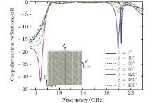
Figure 4 gives the simulated co-polarization reflection versus frequency with different incident azimuth angles under LCP wave incidence, in which the inset is used to describe the incident azimuth angles. The incident angle is fixed to be 45° . It can be found that in the considered frequency range 9.2 GHz– 17.7 GHz, the co-polarization reflection is independent of the incident azimuth angles. The highly efficient co-polarization reflection can be achieved under arbitrary incident azimuth angles. This is the most important advantage compared with the conventional method.
Fig. 4. The simulated co-polarization reflection versus frequency with different incident azimuth angles at a fixed incident angle θ i = 45° .
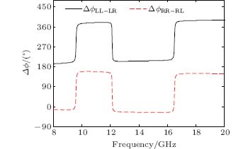
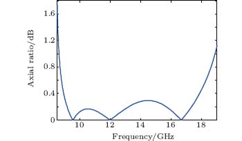
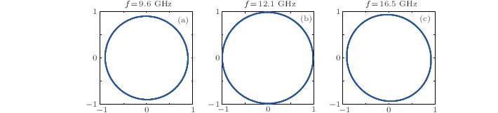
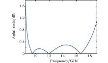
The wide-band performance results from the superposition of multiple polarization conversion peaks around 9.6 GHz, 12.1 GHz, and 16.5 GHz corresponding to the three resonant frequencies. Figure 5 gives the phase differences between the co- and cross-polarization reflections under LCP and RCP wave incidence. We can find that at these resonant frequencies, the phase shifts of co-polarization reflections with respect to cross-polarization reflections have a π phase jump. Under oblique incidence, the co-polarization reflections are almost consistent with that under normal incidence except a tiny fall-down at f = 11.0 GHz. The bandwidth increases with increasing incident angles. Figure 6 gives the axial ratio of the reflected waves under LCP illumination from 8.5 GHz to 19.0 GHz, which is calculated from the co- and cross-polarization reflections for both x- and y- polarized wave incidence. From the calculated results, the axial ratio in the range of whole frequency is mostly below 3 dB. This indicates that the reflected waves can be viewed as actual CP waves. In fact, the axial ratio of the reflected wave has something to do with the co-polarization reflectivity. The axial ratio decreases with increasing co-polarization reflection, which will be 0 dB if the co-polarization reflection is 100%. Therefore, the three axial ratio dips correspond well with the three co-polarization peaks in Fig. 3. Figure 7 gives the polarization ellipses of the reflected waves at the three co-polarization peaks under LCP wave illumination. From the figure, we can find that the three ellipses can be approximately regarded as circles at the three resonant frequencies.
Fig. 7. The polarization ellipses for the reflected waves under LCP wave incidence at the three co-polarization reflection peak frequencies, the axes represent the normalized magnitude of the electric fields at any two orthogonal directions. (a) f = 9.6 GHz, (b) f = 12.1 GHz, (c) f = 16.5 GHz.
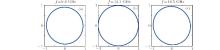
In order to observe the polarization state more clearly, we draw the tracking curve of the end of the electric field vector and obtain the spatial view of the polarization for incident LCP waves and the reflected waves at the frequency f = 16.5 GHz as shown in Fig. 8. Figure 8(a) is for incident LCP wave, which is propagating along the – z direction of the black arrow shown. Figure 8(b) is for the reflected wave reflected by a metal plate, which is propagating along the + z direction of the black arrow shown. It is right-handed circularly polarized. Figure 8(c) is for the reflected waves reflected by the designed metasurface, which is LCP wave propagating also along the + z direction as the black arrow shown.
Fig. 8. Spatial view of polarization for incident and reflected waves, (a) for incident LCP wave, (b) for reflected RCP wave by metal plate, and (c) for reflected LCP wave by metasurface.
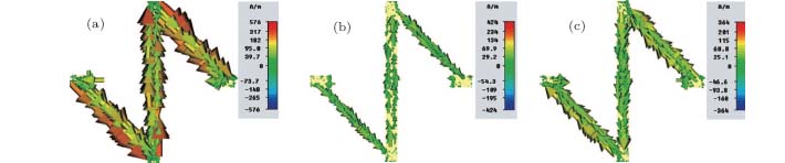
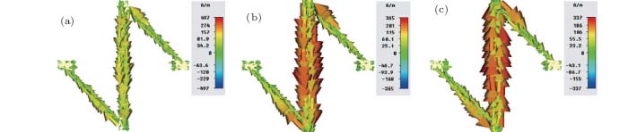
The simulated surface current distributions on N-shaped pattern array are shown in Figs. 9 and 10 for LCP and RCP wave incidence, respectively. Figures 9(a) and 10(a), figures 9(b) and 10(b), and figures 9(c) and 10(c) correspond to f = 9.6 GHz, f = 12.1 GHz, and f = 16.5 GHz, respectively. The surface current distribution agrees well with our analysis in Fig. 3. The equivalent currents in x and y directions are different. The surface current resonates with the incident electric fields and produces reflected and transmitted electric fields which have phase changes with respect to the incident electric fields. The phase changes in x and y directions have different values owing to the different equivalent currents in these two directions as described in Fig. 3.
Fig. 10. Surface current distributions under RCP waves incident, (a) f = 9.6 GHz, (b) f = 12.1 GHz, (c) f = 16.5 GHz.
Supposing that the reflected electric fields in x and y directions under LCP wave incidence are Erx and Ery, respectively. They can be expressed as
For the y-polarized incident LP waves, the reflected waves can be divided into two parts (Ryy, Ryx), and the reflected waves for x-polarized incident LP waves also have two parts (Rxx, Rxy), where Ryy and Ryx, denote the complex reflected coefficient of y-polarized and x-polarized reflected waves under y-polarized wave incidence. Similar definitions are for Rxx and Rxy. The amplitudes of the reflection coefficient are represented by ryy, ryx, rxx, and rxy, respectively. Denoting the phases of the reflection coefficient by ϕ yy, ϕ yx, ϕ xx, and ϕ xy, respectively, the electric field of the reflected waves can be described in the following reflection matrix:
Then, the reflected electric field can be written as
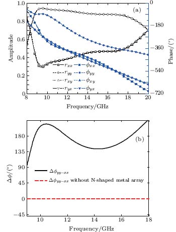
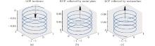
From the above expression, there are four cases: For convenience, they are expressed as RxxRyy, RxyRyx, RxxRyx, and RxyRyy, respectively. The latter two cases RxxRyx and RxyRyy express the reflected LP wave under CP wave incidence, while RyyRxx and RyxRxy are the theoretically possible co-polarization terms for CP wave incidence. By analysis of the necessary conditions for co-polarization reflection under CP wave incidence, the 90 degree phase delaying relationship between the electric field components in x and y directions can be converted mutually under conditions ϕ yy – ϕ xx = ± π or ϕ yx – ϕ xy = 0. Under these conditions, the circular polarization-keeping reflection is realized due to the reversed propagation direction. To confirm this interpretation, numerical full-wave simulations are carried out to calculate the amplitudes and phases of the co- and cross-polarization reflections for both x- and y-polarized wave normal incidence. The calculated results are given in Fig. 11(a), in which the left axis denotes the amplitudes and the right axis represents the phase. From the figure, it is revealed that the cross-polarization reflection is considerably larger than the co-polarization reflection. Thus, this proposed CP-keeping metasurface works both in RxxRyy case and RxyRyx case and RxyRyx dominates the CP-keeping reflection. It is easily found that the phase difference of the cross-polarization reflections under x- and y-polarized wave incidence is zero. In addition, the phase differences of the co-polarization reflections for x- and y-polarized wave incidence onto the metasurface with and without the N-shaped metallic array are given in Fig. 11(b). From the figure, ϕ yy has an approximate π -phase-shift to ϕ xx over the frequency range from 9.2 GHz to 17.7 GHz when the metasurface is illuminated. At the three tips for the co-polarization reflection (f = 9.6, 12.1, and 16.5 GHz), ϕ yy – ϕ xx = π , the co-polarization-keeping reflection is up to 100%. In contrast, there is no phase change between ϕ yy and ϕ xx when the N-shaped metallic pattern array is removed. Therefore, the results simulated are in accordance with that of theoretical analysis.
Fig. 11. (a) The simulated amplitudes and phases of the co- and cross-polarization reflections for both x- and y-polarized waves incidence, (b) phase differences of the co-polarization reflection coefficients under x- and y-polarized waves incidence.
4. Experimental verification
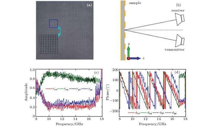
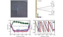
In order to verify this designed circular polarization-keeping reflective metasurface, a sample with dimensions 312 mm× 312 mm is fabricated using the conventional print circuit board (PCB) technique. The photograph of the sample is shown in Fig. 12(a), in which the inset is a zoom view of a 8× 8 unit cells. A 3-mm thick F4B substrate was used and the copper pattern surfaces were tinned in order to protect them from being oxidized. Figure 12(b) gives the schematic illustration of the reflection measurement setup. The sample is irradiated by one of the two linearly polarized horn antennas while the other antenna is worked as a receiver to receive the reflected linearly polarized waves. The separation angle between the two antennas is set to be 8° in order to carry out the normal incidence measurement in the experiment. The horn antenna is capable of transmitting or receiving both x- and y-polarized waves by placing the antenna on its shorter and longer sides, respectively. Firstly, a metal ground sheet with the same size as the reflective metasurface is measured for the sake of normalization. Then, the amplitudes and phases for both the co- and cross-polarization reflections can be measured. In this way, rxx, rxy, ryx, ryy, ϕ xx, ϕ xy, ϕ yx, ϕ yy are measured in the frequency range from 8 GHz to 18 GHz. The measured amplitudes and phases are, respectively, given in Figs. 12(c) and 12(d). The measured co- and cross-polarization reflection under LCP illumination is given in Fig. 13, which is calculated from the measured amplitudes and phases of the co- and cross-polarization reflections under both x- and y-polarized waves incidence. It can be seen in the figure that the co-polarization reflection is up to 97% over the frequency range from 9.8 GHz to 16.8 GHz. The measured co-polarization reflection is in good accordance with the simulation results.
Fig. 12. (a) The photograph of the fabricated sample (size: 312 mm× 312 mm), (b) schematic program of measurement setup, the measured amplitudes (c) and phases (d) of the cross- and co-polarization reflections under x- and y-polarized waves incidence.
Fig. 13. The measured co- and cross-polarization reflections for CP wave incidence.
5. Conclusions
In this paper, a circular polarization-keeping reflection base on reflective metasurface with sub-wavelength thickness is proposed and designed using the N-shaped electric dipole-like resonator. This reflective metasurface can realize wide-band and highly efficient polarization-keeping reflection under LCP and RCP waves incidence. The polarization manipulation using this metasurface is produced by different abrupt phase changes in x and y directions. The simulated results indicate that under normal incidence, the co-polarization reflection for CP waves is larger than 98% from 9.2 GHz to 17.7 GHz and the band-width is expanded as the incident angle increases. Most importantly, the co-polarization reflection is independent of the incident azimuth angles. The experimental results have good consistency with the simulated results. Because of easy realization and ultra-thin thickness, this metasurface provides a convenient way of achieving wide-band and highly efficient circular polarization-keeping reflection under CP wave incidence. The proposed CP-keeping reflection metasurface could be used to achieve high-efficiency reflective CP phase gradient metasurface. Some applications in target tracking and circular-polarization detecting can be envisaged.
GradyN K, HeyesJ E, ChowdhuryD R, ZengY, ReitenM T, AzadA K, TaylorA J, DalvitD A R and ChenH T2013Science3401304DOI:10.1126/science.1235399[Cited within:2]
2
YuN F, GenevetP, KatsM A, AietaF, TetienneJ P, CapassoF and GaburroZ2011Science334333DOI:10.1126/science.1210713[Cited within:]
3
SunY Y, HanL, ShiX Y, WangZ N and LiuD H2013Acta Phys. Sin. 62104201(in Chinese)DOI:10.7498/aps.62.104201[Cited within:1][JCR: 1.016][CJCR: 1.691]
... [1] The polarization selectivity and convertibility were simultaneously achieved by integrating the asymmetric split-ring resonators with the S-shape resonators in Ref ...
2011
1
2013
1.016
1.691
1
2014
1.148
1.2429
1
2014
1.016
1.691
... 5] It is considered as a single surface with a negligible sub-wavelength thickness, rather than frequency selective surfaces ...
1
1999
0.0
0.0
... Many studies on applications of metasurfaces have been implemented with distinct advantages over conventional methods, such as planar antennas, reflectarrays,[6] phase gradient metasurface,[7,8] and polarization converter ...
1
2012
13.025
0.0
... Many studies on applications of metasurfaces have been implemented with distinct advantages over conventional methods, such as planar antennas, reflectarrays,[6] phase gradient metasurface,[7,8] and polarization converter ...
1
2012
3.794
0.0
... Many studies on applications of metasurfaces have been implemented with distinct advantages over conventional methods, such as planar antennas, reflectarrays,[6] phase gradient metasurface,[7,8] and polarization converter ...
1
2012
0.0
0.0
... [9#cod#x2013 ...
1
2011
0.0
0.0
... [10] A light polarization converter using a silver film with array of perforated S-shaped holes was realized to freely modulate the polarization angle ...
Filamentary discharges in dielectric barrier discharge operating in a glow regime are studied by use of two-dimensional particle-in-cell simulation with Monte Carlo collisions included. The formation of multiple filaments and the involved electric fields, electric potentials, plasma densities, and particle temperatures are presented. It is found that the filaments are not ignited simultaneously, and they expire with the shift of the plasma sheaths. "Dark discharges", which produce ion densities lower by one order of magnitude than a typical filamentary discharge, are observed while the filaments from earlier discharges are decaying. (C) 2013 American Institute of Physics. [http://dx.doi.org/10.1063/1.4794824]
... [14] In general, there are few papers on circular polarization (CP) conversion, compared with the linear polarization (LP) conversion and linear-to-circular polarization conversion ...
Effects of an ultra-strong magnetic field on electron capture rates for Co-55 are analyzed in the nuclear shell model and under the Landau energy levels quantized approximation in the ultra-strong magnetic field, and the electron capture rates on 10 abundant iron group nuclei at the surface of a magnetar are given. The results show that electron capture rates on Co-55 are increased greatly in the ultra-strong magnetic field, by about 3 orders of magnitude generally. These conclusions play an important role in future study of the evolution of magnetars.
Du Jun 1 ;Li Ping-Ping 1 ;Luo Xia 1,2 ;
Effects of ultra-strong magnetic field on electron capture rates for 55 Co are analyzed in the nuclear shell model and under the Landau energy levels quantized approximation in the ultra-strong magnetic field, and the electron capture rates on 10 abundant iron group nuclei at the surface of magnetar are given. The results show that electron capture rates on 55 Co are increased greatly in the ultra-strong magnetic field, by about 3 orders of magnitude generally. These conclusions play an important role in future studying the evolution of magnetar.
1
2011
1.016
1.691
1
2012
1.016
1.691
1
2014
0.71
0.0
... 19] Conventional polarization manipulation at microwave frequencies is always realized using chiral materials or multilayered metallic structures and suffers from the bulky volumes, high losses, and narrow bandwidth ...
1
2007
3.546
0.0
... [20#cod#x2013 ...
1
1973
0.0
0.0
1
1999
0.0
0.0
1
2007
7.943
0.0
1
2008
3.794
0.0
1
2010
0.0
0.0
... 25] In this regard, metasurfaces were proposed to implement polarization control ...
Wide-band circular polarization-keeping reflection mediated by metasurface*


