Broadband perfect polarization conversion metasurfaces*
Cite this Article
Chen Hong-Ya, Wang Jia-Fu, Ma Hua, Qu Shao-Bo, Zhang Jie-Qiu, Xu Zhuo, Zhang An-Xue. Broadband perfect polarization conversion metasurfaces* . Chinese Physics B, 2015, 24(1): 014201 
Permissions
Broadband perfect polarization conversion metasurfaces*
Corresponding author. E-mail: mahuar@163.com
Corresponding author. E-mail: qushaobo@mail.xjtu.edu.cn
Project supported by the National Natural Science Foundation of China (Grant Nos. 61331005, 11204378, 11274389, 11304393, and 61302023), the National Science Foundation for Post-doctoral Scientists of China (Grant Nos. 2013M532131 and 2013M532221), the Natural Science Foundation of Shaanxi Province, China (Grant No. 2013JM6005), and the Aviation Science Foundation of China (Grant Nos. 20132796018 and 20123196015).
Abstract
We propose a broadband perfect polarization conversion metasurface composed of copper sheet-backed asymmetric double spilt ring resonator (DSRR). The broadband perfect polarization convertibility results from metallic ground and multiple plasmon resonances of the DSRR. Physics of plasmon resonances are governed by the electric and magnetic resonances. Both the simulation and measured results show that the polarization conversion ratio (PCR) is higher than 99% for both x- and y-polarized normally incident EM waves and the fractional bandwidth is about 34.5%. The metasurface possesses the merits of high PCR and broad bandwidth, and thus has great application values in novel polarization-control devices.
Keyword:
42.25.Bs; 42.25.Ja; 78.67.Pt; 92.60.Ta; metasurface; perfect polarization conversion; multiple plasmon resonances
1. Introduction
Polarization state is one of the important properties of electromagnetic (EM) waves. Currently, the birefringence effect and optical activity of natural materials have been widely applied in polarization control. Unfortunately, conventional methods of controlling polarization are limited by bulky volumes.[1] Miniaturized devices are needed for practical applications. Metamaterials[2– 7] are composed of sub-wavelength resonators, which have unconventional EM responses that are unattainable in the natural material. Therefore, EM polarization states are able to be controlled and manipulated freely based on metamaterials in the sub-wavelength scale. More interestingly, the two-dimensional metamaterials (also called metasurfaces) are used to achieve high-performance polarization rotators.[8– 16] They have been studied experimentally and theoretically for both reflective and transmissive polarization rotators. A terahertz linear polarization rotator was demonstrated using metal cut-wire array.[8] Its conversion efficiency is higher than 80% due to constructive interferences from the Fabry– Pé rot-like cavity. A highly efficient broadband polarization transformation slab was achieved by stacking twisted complementary circular symmetric split-ring resonators.[9] An optically thin quarter-wave plate was proposed based on plasmonic metasurfaces that generate high-quality circularly polarized light over a broad wavelength range for arbitrary orientation of linear polarization.[10] Broadband polarization rotator was demonstrated based on multi-order plasmon resonances and high impedance surfaces.[11] A special optical polarization control is generated by the particular electric and magnetic resonances in the optical metamaterial.[12] However, till now, polarization rotators based on metasurfaces with near-unity conversion efficiency as well as broad operating bandwidth are difficult to implement, which are very desirable for practical applications.
In general, the conversion efficiency and operating bandwidth of reflective polarization rotators can be improved greatly using multilayer structures.[9, 17, 18] However, this inevitably increases the total volume of the polarization rotators. In this letter, we propose to achieve a very high-efficiency and broadband polarization rotator using reflective metasurfaces based on multiple plasmon resonances. A broadband perfect polarization rotator is designed and demonstrated experimentally at the microwave regime. The polarization conversion metasurface is composed of asymmetric double spilt ring resonator (DSRR), which has multiple resonant frequencies to extend the operating bandwidth. The simulated results show that this rotator is capable of rotating linear polarization to its orthogonal one for both x- and y-polarized normally incident EM waves. The measured results are in good agreement with the simulation results. The rotation efficiency is higher than 99% in a broad band from 9.1 GHz to 12.9 GHz.
2. Theory design
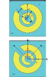
The metasurface unit cell is composed of concentric DSRR and metallic ground sheet separated by an F4B-2 dielectric spacer, as shown in Fig. 1(a). The dielectric spacer is 3 mm thickness with a dielectric constant ε r = 2.65 and a loss tangent tanδ = 0.001. The periodicity of the metasurface unit cell is 6 mm. The other parameters of DSRR structure are: the radius of outer and inner rings R1 = 2.4 mm, R2 = 1.4 mm, r1 = 1.0 mm, r2 = 0.5 mm, the split width w = 1.0 mm, w1 = 0.5 mm, and the metal thickness t = 0.017 mm. For the sake of analyzing the physical mechanism, the DSRR used in our design has a symmetric axis defined by the v axis along 45° direction with respect to y direction as shown in Fig. 1(b). Therefore, our metasurface can be seen as an anisotropic homogeneous metamaterial layer with a dispersive relative permeability tensor and a relative permittivity, put on top of a metallic ground. We use the u and v axis to mark the metasurface anisotropic axes.
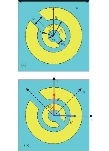 | Fig. 1. (a) Front view of metasurface unit cell. (b) The x and y axes are used to mark incident EM wave direction, while u and v axes are used to mark the metasurface anisotropic axis. |
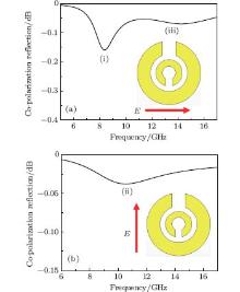
Consider a normally incident y-polarized EM wave E. Just like other DSRR structures, [19] the meatasurface unit cell possesses multiple plasmon resonances by interacting with incident EM wave E. In order to understand the physical principle of multiple plasmon resonances, we analyze the plasmon resonance eigen-modes of DSRR by full-wave simulations performed with CST Microwave Studio. Figure 2 shows the spectra of co-polarization reflection versus frequency under normal incidence. The reflection spectra clearly show that there are in all three dips for the co-polarization reflection, which predicts the presence of plasmon resonance eigen-modes. Eigen-modes (i) and (iii) are excited when E is perpendicular to the split gap (that is, along the u axis) as shown in Fig. 2(a), while eigen-mode (ii) is excited when E is parallel to the split gap (that is, along the v axis) as shown in Fig. 2(b). When E is parallel to the y axis as shown in Fig. 1(b), the incident electric fields can be decomposed into two orthogonal components, which excite independently their corresponding resonance eigen-modes. In this way, three resonances can be excited due to simultaneous excitation of the above three eigen-modes of DSRR.
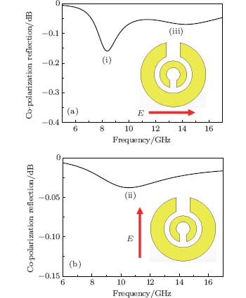 | Fig. 2. Eigen-modes of DSRR under normal incidence: (a) E is perpendicular to the split gap, (b) E is parallel to the split gap. |
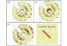
To further understand the physics of three plasmon resonance eigen-modes, the surface currents on DSRR are monitored at the three eigen-frequencies, as shown in Fig. 3. Since the outer and inner rings can be considered as evolved from cut-wire resonators, they have similar electric response as shown in Figs. 3(a) and 3(b). Therefore, the eigen-modes (i) and (iii) mainly result from electric resonance of outer and inner rings, respectively. As shown in Fig. 3(c), anti-parallel surface currents are induced on the DSRR and metallic ground, which means that the magnetic coupling is generated in the metasurface unit cell. Hence, eigen-mode (ii) results from the typical magnetic resonance. Therefore, these three plasmon resonances of DSRR result from the electric and magnetic responses, leading to extended bandwidth of cross-polarization reflection.
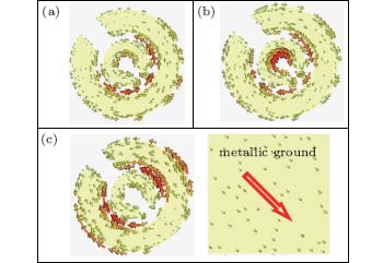 | Fig. 3. Induced surface current distributions on the DSRR at the three eigen-frequencies. (a): eigen-mode (i), (b): eigen-mode (iii) and (c): eigen-mode (ii). |
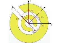
At electric resonance frequency (i) and (iii), the electric dipoles are excited along DSRR which possess both x-polarized (px) and y-polarized (py) components. According to the superposition theorem of EM field, E and py result in co-polarization reflection, while px results in cross-polarization reflection. For magnetic resonance frequency, Figure 4 gives an intuitive image of y-polarized incident wave rotated to x-polarized reflection wave. When y-polarized incidence EM waves illuminate on the metasurface, it has two orthogonal equal components, that is, Eui = Evi. Component Evi excites the magnetic resonance. Thus, at resonance frequency, reflective components Evr and Eur are generated by out-phase and in-phase reflection, [12, 16] respectively. Hence, the y-polarization incident wave is converted to x-polarization reflection, as shown in Fig. 4.
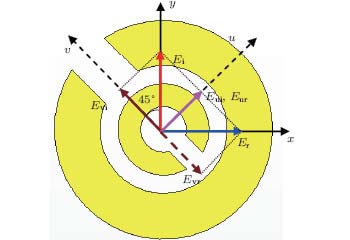 | Fig. 4. Intuitive image of y-to-x polarization conversion at the magnetic resonance frequency. |
In general, the resonance frequencies can be shifted by the geometries of DSRR. Thus, by means of adjusting the geometries, a broadband perfect reflective polarization rotator can be gained. It is noted that when x-polarized waves normally illuminate on the metasurface, it also excites the same plasmon resonances leading x-to-y polarized reflection wave with the same conversion efficiency. Therefore, we only need to demonstrate y-to-x polarized reflection both numerically and experimentally.
3. Simulation results
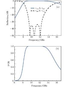
In order to verify broadband and perfect conversion properties, full-wave simulations are performed with CST Microwave Studio. We define cross- and co-polarization as rxy = | Exr/Ei| and ryy = | Eyr/Ei| for y-polarized incidence, respectively. Then, the polarization-conversion ratio (PCR) can be defined as PRC = | rxy| 2/(| rxy| 2+ | ryy| 2) for y-to-x polarization conversion. Figure 5 shows the simulated reflection and PRC versus frequency. As shown in Fig. 5(a), the cross-polarization reflection rxy approaches 0dB from 9.1 GHz to 12.9 GHz, while the co-polarization reflection ryy is reduced by more than 20 dB. Therefore, the PCR is higher than 99% at this frequency regime, as shown in Fig. 5(b). That means a nearly perfect 90° polarization rotation is achieved within this frequency regime for both x-polarized and y-polarized incident EM waves. The bandwidth of nearly perfect polarization conversion is about 34.5% with respect to the central frequency. As analyzed above, the broadband perfect properties result from three closely neighboring resonance frequencies (9.57 GHz, 10.6 GHz, and 12.02 GHz).
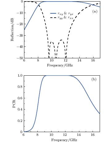 | Fig. 5. Simulated results of (a) the co- and cross-polarization reflections and (b) polarization– conversion ratio. There are three plasmon resonances: (i) f = 9.57 GHz, (ii) f = 10.6 GHz, and (iii) f = 12.02 GHz. |
4. Experiment results
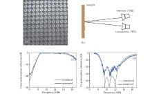
In order to further validate the design, we fabricated a sample and measured the cross- and co- polarization reflection using Agilent E8363B network analyzer. Figure 6(a) shows the prototype of the fabricated sample with an area of 402× 402 mm2. Figure 6(b) gives a schematic illustration of the reflection measurement method. Two horn antennae are set symmetrically with respect to the normal with a small angle of 6° . One of the antennae acts as transmitter while the other one as receiver. The cross- and co-polarization reflection can be measured. Figures 6(c) and 6(d) give the measured cross- and co- polarization reflection, respectively. As shown in Figs. 6(c) and 6(d), the measured results agree very well with the simulated ones. There are three closely adjacent resonance frequencies in the reflection curve, despite the minor blue-shift of the latter two resonance frequencies owing to finite size of the sample. The cross-polarization reflection is very close to 0dB while the co-polarization reflection is reduced by more than 20dB for both x- and y- polarized incident EM waves. Therefore, the measured PCR is also higher than 99% with nearly the same bandwidth as the simulated one.
 | Fig. 6. The fabricated sample and measured reflection spectra: (a) the fabricated sample, (b) schematic of measurement setup, (c) measured cross-polarization and (d) co-polarization reflection versus frequency under normal incidence. |
5. Conclusion
In conclusion, a broadband perfect 90° polarization conversion metasurface is proposed and demonstrated by both simulation and experiment. The broadband perfect conversion metasurface is composed of asymmetric DSRR unit cells. By means of making three close-neighboring plasmon resonances, high-efficiency cross-polarization reflection and very low co-polarization reflection are achieved. Both the simulated and measured results are in good accordance. Because of the broadband perfect polarization conversion property, such polarization conversion metasurfaces are of great application values in the polarization-controlled devices, stealth surfaces, antennas, etc.
Reference
| 1 |
|
| 2 |
|
| 3 |
|
| 4 |
|
| 5 |
|
| 6 |
|
| 7 |
|
| 8 |
|
| 9 |
|
| 10 |
|
| 11 |
|
| 12 |
|
| 13 |
|
| 14 |
|
| 15 |
|
| 16 |
|
| 17 |
|
| 18 |
|
| 19 |
|