Liu Guo-Chang, Li Chao, Fang Guang-You. Experimental demonstration of an invisible cloak with irregular shape by using tensor transmission line metamaterials* . Chinese Physics B, 2015, 24(1): 014101
Permissions
Experimental demonstration of an invisible cloak with irregular shape by using tensor transmission line metamaterials*
Liu Guo-Chang, Li Chao†, Fang Guang-You
Key Laboratory of Electromagnetic Radiation and Sensing Technology, Chinese Academy of Sciences, Beijing 100190, China
Project supported by the National Natural Science Foundation of China (Grant Nos.11174280, 60990323, and 60990320) and the Knowledge Innovation Program of the Chinese Academy of Sciences (Grant No.YYYJ-1123).
Abstract
We present the design and the experimental demonstration of an invisible cloak with irregular shape by using tensor transmission line (TL) metamaterials. The fabricated cloak consists of tensor TL unit cells exhibiting anisotropic effective material parameters, while the background medium consists of isotropic TL unit cells. The simulated and the measured field patterns around the cloak show a fairly good agreement, both demonstrate that the fabricated cloak can shield the cloaked interior area from electromagnetic fields without perturbing the external fields. The scattering of the cloaked perfect electric conductor (PEC) is minimized. Furthermore, the nonresonant property of the TL structure results in a relatively broad bandwidth of the realized cloak, which is clearly observed in our experiment.
Transformation optics (TO)[1, 2] has provided a way to control the electromagnetic (EM) field freely, thereby offering the potential to design lots of devices with novel properties.[3, 4] Its most notable application is the cloak of invisibility, [1, 2] which can shield an interior area from EM fields without perturbing the external fields. However, it is challenging to implement such a classic cloak even by using metamaterials (MTMs), because the required constituent parameters are inhomogeneous and anisotropic. The first experimental breakthrough was a two-dimensional (2D) traverse electric (TE) cloak with reduced parameters at microwave frequencies.[5] The cloak was fabricated by using split-ring resonators (SRRs), which inherently lead to a narrow bandwidth. Hereafter, a nonmagnetic 2D cloak at optical frequencies was reported.[6] Since the angular component of the permittivity is not achieved with a desired distribution, it is also a reduced parameter cloak. The first full parameter cloak was realized by using transmission line metamaterials (TL MTMs).[7] It is a 2D cylindrical cloak constructed with curved unit cells to realize material tensors that are diagonal in the cylindrical basis. Recently, a 2D hexagonal cloak at optical frequencies was presented, which can only work for six incident directions.[8] The linear homogeneous transformation method leads to homogenous and finite material parameters in the cloak. However, it is still a parameter reduced cloak fabricated by using six calcite trapezoids glued together.
In view of the difficulty to realize the free-space cloaks, a ground-plane cloak was proposed based on the optical transformation, which can hide any objects under a ground plane covered by an MTM carpet.[9] Many versions of carpet cloak have been reported for both microwave and optical frequencies.[10– 26] By contrast, experimental achievements of the free-space cloak are much less, and by now all of the previously reported experiments are limited to 2D symmetric objects, [5– 8, 27] four of which are with cylindrical shapes, [5– 7, 27] and the remaining one is with hexagonal shape but simplified parameters as mentioned above.[8]
In this paper, we design and fabricate a 2D free-space cloak with irregular shape using tensor TL MTMs.[28] The material tensors for implementing such an irregular cloak are achieved by precise control of all the different branches of the tensor TL unit cells. By taking advantage of the full tensor realization, the cloaking effect of shielding an interior area from EM fields without perturbing the external fields is verified. The nonresonant property of the TL structure leads to a relatively broad bandwidth of the realized cloak, which can be clearly observed in our experiment.
2. Design and realization of an invisible cloak with irregular shape
2.1. Design of an invisible cloak with irregular shape
An irregular invisible cloak with inner boundary defined by R(θ ) and outer boundary defined by τ R(θ ) is first designed, and the general expressions for the material parameters are deduced. The tensor components of the relative permittivity can be expressed as[29]
and ɛ xz = ɛ yz = ɛ zx = ɛ zy . The permeability is μ = ɛ . Here τ represents the linear compressing ratio. In this paper, without loss of generality, the irregular shape of the fabricated cloak is defined as
Under the illumination of a TE polarized wave (electric polarized in the z direction), only μ xx, μ xy, μ yx, μ yy, and ɛ zz are of interest. By using Eq.(1), the required material parameters can be calculated, which are shown in Fig. 1. The required permittivity and permeability of such an irregular cloak are both inhomogeneous, and the permeability is also anisotropic. The parameters vary in large ranges, i.e., μ xx varies from 0.20 to 35.91, μ xy = μ yx varies from – 13.21 to 14.39, μ yy varies from 0.08 to 156.81, and ɛ zz varies from 0.01 to 1.44. Specific minimum and maximum values are set to clearly show the distributions of the parameters, as given in the four color bars of the figure. Values less than the minimum (greater than the maximum) are mapped to the minimum (the maximum). On the other hand, the special shape makes it almost impossible to transform the material tensor to a diagonal matrix in the primary axis coordinate system, then the most commonly used simplified parameter[5] for implementing cloaks is no longer available. In summary, it is a very challenging work to implement such a cloak with irregular shape due to the complexity of the required material parameters.
Fig. 1. Parameter distributions of an invisible cloak with irregular shape: (a) μ xx, (b) μ xy = μ yx, (c) μ yy, and (d) ɛ zz.
2.2. Irregular invisible cloak achieved by TL MTMs
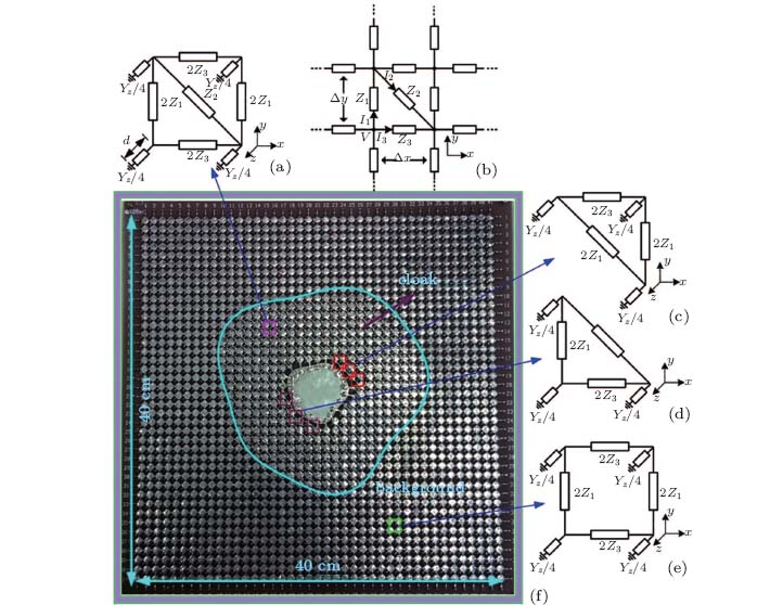
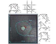
In this paper, the specific material parameters for the irregular cloak are achieved by using tensor TL MTMs. TL MTMs were initially limited to synthesize materials whose material parameters are diagonal matrixes.[7, 30– 32] In this paper, a new kind of TL MTMs[28] is applied to fabricate the anisotropic and inhomogeneous cloak with irregular shape. Its unit cell is shown Fig. 2(a). A diagonal branch is introduced into the conventional rectangle topology, [30] which changes the coupling mode between the voltage difference along the z direction and the surface currents in the x– y plane, and then contributes to the off-diagonal components of the effective material tensors. So the unit cell can exhibit effective anisotropic material parameters with off-diagonal components. Figure 2(b) shows the top view of a large piece of TL MTM constituted by these unit cells.
Fig. 2. (a) TL MTM unit cell to mimic the cloak shell. (b) A large piece of TL MTM constituted by the unit cell shown in panel (a). (c)– (d) TL MTM unit cells to mimic the inner boundary of the cloak. (e) TL MTM unit cell to mimic the background. (f) The real experimental cloak device with irregular shape.
By deriving the TL network equations using Kirchhoff’ s laws to the neighboring unit cells, the dispersion relation can be found
Here, Zxy = Zyx is pre-assumed, and the impedances satisfy the following expression:
The dispersion relation of an anisotropic medium can be derived using Maxwell’ s equations under the presumption that the incident wave is TE mode
where μ xy = μ yx is pre-assumed. The effective parameter ɛ z is only determined by the admittance Yz in the z direction
the introduction of the diagonal branch will not change the above relationship.[30]
Combining Eqs. (3), (5), and (6), we can derive the mapping between the retrieved material parameters (the effective permittivity and permeability) and the TL circuit parameters (the elements’ impedances and admittances)
By substituting Eq. (7) to Eq. (4), the relationship between the TL circuit parameters and the material parameters can be obtained
which is to used in the design.[32] According to Eq. (8), materials with specific anisotropic and inhomogeneous parameters can be modeled by the tensor TL MTM shown in Fig. 1(a). We can then artificially synthesize the irregular cloak with precise control of the circuit parameter distributions for the tensor TL network.
For the case μ yx = μ xy = 0, equation (8) can degenerate to the following form:
where Z2 = ∞ means that the diagonal branch in Fig. 2(a) is removed and the unit cell degenerates to the conventional non-diagonal topology in Fig. 2(e).
In this paper, the tensor TL MTM unit cell exhibiting anisotropic effective material parameters shown in Fig. 2(a) is employed to mimic the cloak shell, and the conventional TL MTM unit cell shown in Fig. 2(e) is chosen to mimic the background. For the region near the inner boundary of the cloak, the unit cells degenerate to the topology depicted in Figs. 2(c)– 2(d) to follow the shape of the inner boundary.
3. Experimental results and bandwidth of the fabricated irregular cloak
The experimental cloak shown in Fig. 2(f) is fabricated on a grounded flame retardant 4(FR4) substrate with dielectric ɛ r = 4.3 and a thickness of 2 mm. The whole structure contains 40× 40 grids, and each one has uniform dimensions of Δ x = Δ y = 1 cm. The inner cloaked region is inserted with a metal sheet, which is grounded to create an effect of perfect electric conductor (PEC) boundary here. The Bloch impedance[30] is employed to absorb the outward waves at the outer boundaries of the background regions. The design frequency is 51 MHz and the unit cell elements to mimic the background region are set as Z1 = Z3 = j · 2π · 51 e6 · 47 e– 9 and Yz = j · 2 π · 51 e6 · 82e– 12. These parameters result in an effective wavelength of 10 cm in the background region at 51 MHz.
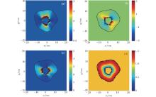
Figure 3 shows the details in the experimental test. The experimental structure is excited with a coaxial connector; the outer conductor of the connector is attached to the ground plane and the center conductor of the connector is attached to the grid node (3, 21). Port 1 of a vector network analyzer (VNA) is connected to the coaxial connector and port 2 is connected to a near-field coaxial probe, which is scanned over the surface of the whole structure. The measured transmission coefficient (S21) is proportional to the voltage of the grid nodes with respect to the ground plane. To eliminate the disturbance of the voltage distribution as the detecting probe touching the node, a broadband amplifier with a high input impedance is inserted between the detecting probe and port 2 of the VNA. The measured input impedance of the amplifier is more than 2 kΩ in the frequency band from 10 MHz to 100 MHz. Figure 4(a) shows the measured results at 51 MHz. For comparison, a simulation is carried out with all the TL parameters exactly the same as in the experiment using commercial software Agilent’ s Advanced Design System simulator (ADS). The simulated results are shown in Fig. 4(b). A fairly good agreement between the measured and the simulated results is found. When a cylindrical TE wave travels through the irregular cloak, the EM waves interact with the cloak and the propagation pattern seems to be squeezed into the irregular cloak shell. The wave fronts separate to pass through the interior area (cloaked area) which is supposed to be hidden, and then restore after leaving it. In this way, the cloak is capable of shielding the interior area from the EM wave without perturbing the external field, the forward and the backward scatterings of the PEC are minimized.
Fig. 4. Simulated and measured node voltage distributions around the cloak with irregular shape at the design frequency 51 MHz: (a) simulated results with excitation at node (3, 21) by ADS, (b) experimental results with excitation at node (3, 21).
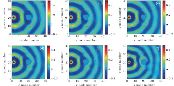
Furthermore, the broadband property of the fabricated cloak can be expected due to the nonresonant nature of the TL MTMs. Figures 5(a)– 5(f) show the performances of the irregular cloak at several equally spaced frequencies with interval 2 MHz in the frequency band from 41 MHz and 53 MHz, excluding the central frequency 51 MHz. The cloaking effects at all the given frequencies are evident, thus the difference between 41 MHz and 53 MHz can be seen as the bandwidth of the fabricated cloak.
Fig. 5. Measured node voltage distributions around the irregular cloak with excitation at node (3, 21) at frequencies: (a) 41 MHz, (b) 43 MHz, (c) 45 MHz, (d) 47 MHz, (e) 49 MHz, (f) 53 MHz.
The cloak with irregular shape designed according to the TO has been proposed for years, but with no experimental verification. This paper is concentrating on demonstrating the validity of the irregular cloak based on TO experimentally. In a practical case, the cloak device should be placed in the free space. For our proposed 2D cloak with irregular shape, it can be connected to the free space by being embedded in a parallel plate waveguide. In this case, the device can hide the cloaked objects in reality for the TE incidence. In this paper, we choose to do a circuit simulation to verify the proposed approach for preliminary study. For the convenience of experiment, the background region is also realized by an LC network. The background region and the lumped LC elements apparently prevent the fabricated cloak from practical use. For the microwave frequency, the lumped LC elements should be replaced by distributed parameter elements, so the TL unit cells may have a microstrip-like structure by proper design. Meanwhile, the dimension of the cloak will reduce to a moderate size, where the background region is no longer needed. Finally, the implemented cloak will become a practical device working in the free space.
The imperfection effects in the experiment are caused by complex factors, including the imperfect welding process, the loss introduced by the non-ideal circuit elements, and the imperfect absorption of outward by the Bloch impedances. Of course, the designed cloak will have a better performance if all the above factors are better controlled.
4. Conclusion
To summarize, we design and fabricate an experimental device to mimic an invisible irregular cloak with full tensor realization. The simulated and the measured results confirm its functionalities of shielding an interior area from the EM waves. The nonresonant property of the TL structure leads to a relatively broadband of the cloak. Other TO devices can also be designed and fabricated by the same way proposed in this paper.
LiC, MengX K, LiuX, LiF, FangG Y, ChenH Y and ChanC T2010Phys. Rev. Lett. 105233906DOI:10.1103/PhysRevLett.105.233906[Cited within:1][JCR: 7.943]
32
LiC, LiuX, LiuG C, LiF and FangG Y2011Appl. Phys. Lett. 99084104DOI:10.1063/1.3629770[Cited within:2][JCR: 3.794]
2
2006
0.0
0.0
... IntroductionTransformation optics (TO)[1,2] has provided a way to control the electromagnetic (EM) field freely, thereby offering the potential to design lots of devices with novel properties ...
... [3,4] Its most notable application is the cloak of invisibility,[1,2] which can shield an interior area from EM fields without perturbing the external fields ...
1
2008
0.0
0.0
... [3,4] Its most notable application is the cloak of invisibility,[1,2] which can shield an interior area from EM fields without perturbing the external fields ...
1
2010
35.749
0.0
... [3,4] Its most notable application is the cloak of invisibility,[1,2] which can shield an interior area from EM fields without perturbing the external fields ...
4
2006
0.0
0.0
... [5] The cloak was fabricated by using split-ring resonators (SRRs), which inherently lead to a narrow bandwidth ...
... 26] By contrast, experimental achievements of the free-space cloak are much less, and by now all of the previously reported experiments are limited to 2D symmetric objects,[5#cod#x2013 ...
... 8,27] four of which are with cylindrical shapes,[5#cod#x2013 ...
... On the other hand, the special shape makes it almost impossible to transform the material tensor to a diagonal matrix in the primary axis coordinate system, then the most commonly used simplified parameter[5] for implementing cloaks is no longer available ...
1
2008
3.385
0.0
... [6] Since the angular component of the permittivity is not achieved with a desired distribution, it is also a reduced parameter cloak ...
3
2009
3.794
0.0
... [7] It is a 2D cylindrical cloak constructed with curved unit cells to realize material tensors that are diagonal in the cylindrical basis ...
... 7,27] and the remaining one is with hexagonal shape but simplified parameters as mentioned above ...
... [7,30#cod#x2013 ...
3
2012
0.0
0.0
... [8] The linear homogeneous transformation method leads to homogenous and finite material parameters in the cloak ...
... 8,27] four of which are with cylindrical shapes,[5#cod#x2013 ...
... [8] ...
1
2008
7.943
0.0
... [9] Many versions of carpet cloak have been reported for both microwave and optical frequencies ...
1
2009
0.0
0.0
... [10#cod#x2013 ...
1
2009
35.749
0.0
1
2009
3.546
0.0
1
2009
27.254
0.0
1
2010
10.015
0.0
1
2010
3.546
0.0
1
2010
0.0
0.0
1
2011
4.063
0.0
1
2011
3.794
0.0
1
2011
7.943
0.0
1
2011
10.015
0.0
1
2011
0.0
0.0
1
2011
3.546
0.0
1
2011
7.943
0.0
1
2011
13.025
0.0
1
2011
3.385
0.0
1
2012
0.0
0.0
... 26] By contrast, experimental achievements of the free-space cloak are much less, and by now all of the previously reported experiments are limited to 2D symmetric objects,[5#cod#x2013 ...
2
2009
0.0
0.0
... 8,27] four of which are with cylindrical shapes,[5#cod#x2013 ...
... 7,27] and the remaining one is with hexagonal shape but simplified parameters as mentioned above ...
2
2010
0.0
0.0
... [28] The material tensors for implementing such an irregular cloak are achieved by precise control of all the different branches of the tensor TL unit cells ...
... 32] In this paper, a new kind of TL MTMs[28] is applied to fabricate the anisotropic and inhomogeneous cloak with irregular shape ...
1
2008
3.546
0.0
... The tensor components of the relative permittivity can be expressed as[29](1a)
4
2003
0.0
0.0
... [7,30#cod#x2013 ...
... A diagonal branch is introduced into the conventional rectangle topology,[30] which changes the coupling mode between the voltage difference along the z direction and the surface currents in the x#cod#x2013 ...
... [30] ...
... The Bloch impedance[30] is employed to absorb the outward waves at the outer boundaries of the background regions ...
1
2010
7.943
0.0
2
2011
3.794
0.0
... 32] In this paper, a new kind of TL MTMs[28] is applied to fabricate the anisotropic and inhomogeneous cloak with irregular shape ...
... [32] According to Eq ...
Experimental demonstration of an invisible cloak with irregular shape by using tensor transmission line metamaterials*


