

Dielectric and magnetic properties of (Zn, Co) co-doped SnO2 nanoparticles
[Rajwali Khan, Fang Ming-Hu† ]
]
]
|
|


†Corresponding author. E-mail: mhfang@zju.edu.cn
*Project supported by the National Basic Research Program of China (Grant Nos. 2015CB921004, 2012CB821404, and 2011CBA00103) and the National Natural Science Foundation of China (Grant Nos. 11374261 and 11204059).
Polycrystalline samples of (Zn, Co) co-doped SnO2 nanoparticles were prepared using a co-precipitation method. The influence of (Zn, Co) co-doping on electrical, dielectric, and magnetic properties was studied. All of the (Zn, Co) co-doped SnO2 powder samples have the same tetragonal structure of SnO2. A decrease in the dielectric constant was observed with the increase of Co doping concentration. It was found that the dielectric constant and dielectric loss values decrease, while AC electrical conductivity increases with doping concentration and frequency. Magnetization measurements revealed that the Co doping SnO2 samples exhibits room temperature ferromagnetism. Our results illustrate that (Zn, Co) co-doped SnO2 nanoparticles have an excellent dielectric, magnetic properties, and high electrical conductivity than those reported previously, indicating that these (Zn, Co) co-doped SnO2 materials can be used in the field of the ultrahigh dielectric material, high frequency device, and spintronics.
The exploration for the diluted magnetic semiconductors (DMS) has significantly increased due to their potential applications in the field of spintronics[1] and optoelectronics[2] devices. Wide band-gap semiconductors, such as SnO2, [3] ZnO2, [4] and TiO2[5] are shown to exhibit DMS behavior by introducing transition metal with 3d electrons in the lattice. Among the most useful and interesting metal oxides, tin dioxide (SnO2) is considered as a promising candidate for the future electrical and electronic industries because it is a wide band-gap semiconductor (Eg = 3.64 eV, 330 K), and has a high dielectric constant and electrical conductivity. Due to these intriguing properties, SnO2 has gained attraction in the field of the high density energy storage material, [6] lithium-ion battery, [7] solid-state gas sensor, and high conductive film, [8] transparent conducting electrode, [9] electro– optical device, [10] transistor, [11] solar cell, [12– 14] and flat panel display.[15] SnO2 is also one of the most important candidate amongst nanomaterials for these applications.[16– 18] Recently, more attention is being given to its DMS behavior at room temperature by doping the transition metals TMs (TMs = Fe, Co, Zn, Ni, Cu, and Mn).[18– 23] High ferromagnetic transition temperature (Tc = 850 K) has achieved in the 1% Fe-doped SnO2, which is one of the highest Tc among the reported ferromagnetic semiconductor oxides.[18] In addition, Co-doped SnO2 polycrystalline samples synthesized successfully by the ball milling method, which exhibits a strong ferromagnetism at room temperature.[24] It is believed that the direct exchange interaction of the delocalized 3d electrons in the TMs-doped semiconductor oxides are the main origin of ferromagnetism.[25] Hays et al. investigated the relationship between the lattice parameter and magnetic property of the Co doped SnO2, and found that its ferromagnetism was suppressed at higher Co doping concentrations.[26] Ogale et al. reported that the room temperature ferromagnetism (RTFM) with a magnetic moment of 7 ± 0.5μ B/Co ion and the coercive field (Hc) of 50 Oe (1 Oe = 79.5775 A· m− 1) have obtained in the (5%– 27%) Co-doped SnO2 thin film.[27] Punnoosea et al. found that the (1%) Co-doped SnO2 has a smaller magnetic moment of 0.133 μ B/Co ion, but a high coercive field (Hc) of 630 Oe and about 31% moderate remanence magnetization (Mr).[28] More recently, Hu Chen-Guo et al. also found RTFM emerging in 1% Co-doped SnO2 with a coercive field (Hc) of 120 Oe and (Mr) of 3.04 × 10− 2 emu/g.[19] The ferromagnetism in the conventional semiconductors have been achieved by the transition metals (TMs) doping.[29, 30] The higher dielectric properties and electrical conductivity of SnO2 are the other important factors for its applications.[31] Although, there are many reports of the theoretical and experimental studies on SnO2, research on the TMs doping in SnO2 is still under discussion. Here, we prepared a series of (Zn, Co) co-doped SnO2 nanoparticles, and studied the effect of this co-doping on its dielectric, transport, and magnetic properties.
The (Zn, Co) co-doped SnO2 nanoparticle samples with Co of 1%, 3%, and 5% concentrations, and Zn (fixed) 5% were synthesized by a chemical co-precipitation method. First 2.5-g SnCl2· 2H2O (0.22 M) was dissolved in 50-ml distilled water and then 30-ml aqueous ammonia solution (2 M) was added to the pervious solution with constant stirring at a pH value between 1 to 10.2.[32] The resulting white precipitates were collected by centrifugation and then washed for five to six times in the distilled water. The washed precipitate was dried at 60 ° C for 24 h in a box furnace. Finally, the synthesized SnO2 nanopowder was annealed at 600 ° C for two hours. For getting (Zn, Co) co-doped SnO2 samples, we added ZnCl2 (0.05 M) and CoCl2· 6H2O with various concentration (x = 0.01 M, 0.03 M, and 0.05 M, respectively) to the SnCl2· 2H2O solution, and let them react in the solution. The samples were characterized by x-ray diffractometer (PAN analytical) using Cu Kα radiation. The GSAS suite of Rietveld programs were used to fit the x-ray diffraction data. The dielectric properties and conductivity as a function of frequency were measured in centered Gold electrode pellet with a typical Impedance analyzer (Agilent 4292) in the frequency range 40 Hz– 15 MHz. DC magnetization measurements were carried out using a Quantum Design superconducting quantum interference device (SQUID) in the temperature range of 2 K– 300 K.
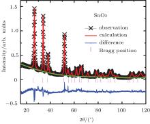
Figure 1 shows the powder x-ray diffraction (XRD) patterns of undoped and co-doped SnO2 samples, indicating that the samples are a single phase without any impurities and crystalize in the tetragonal structure (space group P42/mnm). The doping of Co and 5%-Zn to the parent compound SnO2 did not change its crystal structure.
 | Fig. 1. The XRD patterns for the pure and (Zn, Co) co-doped SnO2 nanoparticle samples with various doping concentrations. |
The obtained lattice parameters by fitting are shown in Fig. 2. The lattice parameters decrease from a = 4.7420(6) Å and c = 3.1895(9) Å , for x = 0 to a = 4.7216(4) Å and c = 3.17932(5) Å , respectively, for doping level of x = 3%. It is consistent with the fact that the ionic radii of Zn2+ (0.060 nm) and Co2+ (0.065 nm) are smaller than that of Sn4+ (0.069 nm) and the valence states of Zn and Co are lower than that of the host Sn4+ cations. It was obvious that the diffraction peaks become weak with Co co-doping, and the peak near 53° gradually disappears and the peak full width at half maximum (FWHM) increases with increasing Co content, indicating that SnO2 lattice distortion occurs due to the difference of the ionic radius of dopant ions.[33] Pure and (Zn, Co) co-doped SnO2 average crystalline size was estimated of 4 nm– 9 nm by analyzing XRD peak widths using Scherrer’ s method.[34]
 | Fig. 2. The XRD pattern of SnO2 and its Rietveld refinements. |
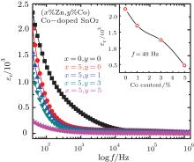
Figure 3 shows the dielectric constant as a function of frequency at room temperature for the undoped and (Zn, Co) co-doped SnO2. In order to measure the capacitance, dielectric loss and AC conductivity as a function of frequency at room temperature, the cylinders (diameter ϕ = 9 mm) with gold electrodes were made by pressing the powder. The dielectric constant was calculated using the following mathematical relation.

where, C is the capacitance, d is the height of the cylinder, A is the pellet cross sectional area, ε r is the relative dielectric constant of the samples, and ε 0 is the dielectric constant of free space. It is obvious that the ε r values for the undoped and doped SnO2 samples monotonously decreases with increasing frequency up to 1 × 10⁴ Hz, while ε r values at higher frequency remain nearly a constant.
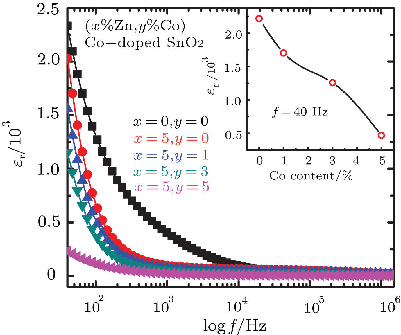 | Fig. 3. The frequency dependence of the relative dielectric constant (ε r) at room temperature for both the pure and (Zn, Co) co-doping SnO2 samples. The inset is the Co doping concentration dependence of the dielectric constant measured at 40 Hz, and room temperature. |
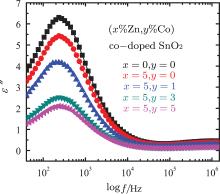
As shown in the inset of Fig. 3, it is obvious that the dielectric constant decreases with Co doping concentration, which may result from the distortion due to smaller radii of Co2+ substituting for Sn4+ , as discussed in Ref. [35]. Figure 4 shows the frequency dependence of the imaginary part (ε ″ ) of dielectric constant, i.e., the dielectric loss, at room temperature. For both pure and (Zn, Co) doped SnO2 samples, the ε ″ (f) exhibits a peak value at a moderate frequency, and remains nearly a constant at higher frequency. Compared with the pure SnO2 sample, (Zn, Co) co-doping results in the decrease of the dielectric loss, and shifting frequency of the loss peak to a lower frequency. Another, as shown in Fig. 5, (Zn, Co) doping results also in the increase of the AC conductivity, especially at higher frequency, which is consistent with the results reported by Chenari.[36] As we know, the increase of frequency can enhance the hopping of the charge carriers.
 | Fig. 4. The frequency dependance of the imaginary part of dielectric constant for both the pure and (Zn, Co) co-doped SnO2 samples. |
For both the pure and (Zn, Co) co-doped SnO2 samples, their AC electrical conductivity follows the formula, [37]

where α AC is the AC electrical conductivity, and ε 0 is the dielectric constant of the free space, ε ″ is the imaginary part of dielectric constant and ω = 2π f, f is the frequency. As clearly given in Eq. (2), the AC conductivity depends only upon the dielectric loss. Consequently, the dielectric loss decreases with the increasing frequency, while the AC conductivity increases. This result is also compatible with the literature, where it is suggested that the increase in α AC with the increasing frequency is attributed to the series resistance effect.[36]
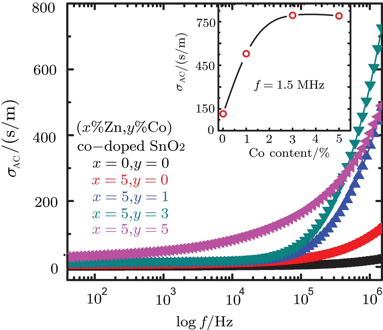 | Fig. 5. The AC conductivity α AC as a function of frequency for both the pure and (Zn, Co) co-doped SnO2 samples. The inset is the Co doped concentration dependence of the AC conductivity measured at 1.5 MHz, and room temperature. |
In fact, there are two possible mechanisms for the increase in α AC: one is the electric energy associated with the high AC frequency which can effectively promote the jumping of charge carriers between the nanoparticles, and the second one is due to the enhanced dielectric relaxation of the polarization of SnO2 nanoparticles in high frequency region.[19, 26]
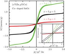
Figure 6 shows the field dependence of the magnetization, i.e., M (H) curves at room temperature for both pure and the (Zn, Co) co-doped samples. The pure and only 5% Zn-doped SnO2 samples exhibit a diamagnetism at room temperature [here its data are not shown]. The co-doped Sn0.95Zn0.05O2 samples, the hysteresis observed in their M (H) curves indicates a ferromagnetic order emerging in the samples. The saturation magnetization (Mr) can reach to 0.201 memu/g for the 1% Co doping sample, and reach a maximum for 3% Co doping sample then decreases in the 5% Co doping sample. The inset of Fig. 6 shows the enlarged hysteresis loop near zero magnetic field, from which a coercive field (Hc) of 50 Oe and a remanent magnetization (Mr) of 0.1 memu/g for 3% Co doping sample are obtained. The lower remanent magnetization (Mr) of 0.0394 memu/g with coercive field (Hc) of 39 Oe was observed in the 5% Co co-doping SnO2 sample. The observed remanent magnetization (Mr) (in 3% Co co-doping) is lower than that reported in Ref. [19]. A ferromagnetic response at lower Co co-doping concentration was also reported in (Fe, Co) co-doped SnO2 by Nomura et al.[38] In our system, ferromagnetic behavior observed even in higher Co doping but the remanent magnetization was decreases at higher Co doping (5%). In addition, the creation of addition charge carriers and oxygen vacancies due to (Zn, Co) co-doping may cause RTFM.[26] However higher cobalt doping may lead to the expansion of SnO2 lattice and the structure disorder, suppressing its ferromagnetism.
 | Fig. 6. The field dependence of the magnetization M (H) measured at room temperature for both the pure and (Zn, Co) co-doped SnO2 samples. The inset is the M (H) curve near zero magnetic field. |
The study on the effect of (Zn, Co) co-doping on SnO2 nanoparticles electrical, dielectric, and magnetic properties were carried out. All the (Zn, Co) co-doping samples have a tetragonal structure. It is found that with the increase of Co doping concentration the dielectric constant and dielectric loss values decrease, but electrical conductivity increases. With the increase of frequency, the dielectric constant and dielectric loss decreases, while electrical conductivity increases. Our results indicate that the limited Co doping can introduce the ferromagnetism in the SnO2 nanoparticles.
| 1 |
|
| 2 |
|
| 3 |
|
| 4 |
|
| 5 |
|
| 6 |
|
| 7 |
|
| 8 |
|
| 9 |
|
| 10 |
|
| 11 |
|
| 12 |
|
| 13 |
|
| 14 |
|
| 15 |
|
| 16 |
|
| 17 |
|
| 18 |
|
| 19 |
|
| 20 |
|
| 21 |
|
| 22 |
|
| 23 |
|
| 24 |
|
| 25 |
|
| 26 |
|
| 27 |
|
| 28 |
|
| 29 |
|
| 30 |
|
| 31 |
|
| 32 |
|
| 33 |
|
| 34 |
|
| 35 |
|
| 36 |
|
| 37 |
|
| 38 |
|