Du Hong-Lei, Xue Qian, Gao Xiao-Yang, Yao Feng-Rui, Lu Shi-Yang, Wang Ye-Long, Liu Chun-Heng, Zhang Yong-Cheng, Lü Yue-Guang, Li Shan-Dong†. Ultrahigh frequency tunability of aperture-coupled microstrip antenna via electric-field tunable BST. Chinese Physics B, 24(12): 127704
Permissions
Ultrahigh frequency tunability of aperture-coupled microstrip antenna via electric-field tunable BST
Du Hong-Leia), Xue Qiana), Gao Xiao-Yanga), Yao Feng-Ruia), Lu Shi-Yanga), Wang Ye-Longb), Liu Chun-Hengc), Zhang Yong-Chenga), Lü Yue-Guangb), Li Shan-Dong†a),d)
College of Physics, Laboratory of Fiber Materials and Modern Textile, the GrowingBase for State Key Laboratory, and Key Laboratory of Photonics Materials and Technology Universities of Shandong, Qingdao University, Qingdao 266071, China
Department of Physics, School of Science, Harbin Institute of Technology, Harbin 150001, China
Northern Institute of Electronic Equipment of China, Beijing 100083, China
National Laboratory of Solid State Microstructures, Nanjing University, Nanjing 210093, China
*Project supported by the National Natural Science Foundation of China (Grant No. 11074040) and the Key Project of Shandong Provincial Department of Science and Technology, China (Grant No. ZR2012FZ006).
Abstract
A composite ceramic with nominal composition of 45.0 wt%(Ba0.5Sr0.5)TiO3–55.0 wt%MgO (acronym is BST–MgO) is sintered for fabricating a frequency reconfigurable aperture-coupled microstrip antenna. The calcined BST–MgO composite ceramic exhibits good microwave dielectric properties at X-band with appropriate dielectric constant ɛr around 85, lower dielectric loss tan δ about 0.01, and higher permittivity tunability 14.8% at 8.33 kV/cm. An ultrahigh E-field tunability of working frequency up to 11.0% (i.e., from 9.1 GHz to 10.1 GHz with a large frequency shift of 1000 MHz) at a DC bias field from 0 to 8.33 kV/cm and a considerably large center gain over 7.5 dB are obtained in the designed frequency reconfigurable microstrip antenna. These results demonstrate that BST materials are promising for the frequency reconfigurable antenna.
With the rapid development of wireless communications, microwave and wireless antennas are widely used in our daily life. Recently, tunable devices, such as tunable antenna, filter, phase shifter, etc., draw increasing attention as they promise better channel selectivity, reduced size, and lower weight since the same hardware can be employed at multiple bands.[1] Among such devices, the frequency reconfigurable (FRC) antennas, whose concept was first raised in 1983, [2] became a potential candidate for improving the channel capacity (or frequency agility). FRC antenna is very significant because one single antenna unit can cover a large working frequency range or works in multiple frequency bands via bias field manipulation. In modern wireless communication systems, significant attention has been shifted toward FRC devices, especially in multiple input multiple output (MIMO) systems, and cognitive radio (CR) systems. The FRC antenna has the flexibility of switching to all the objective frequencies, and thus hopefully replaces many traditional wideband and multiband antennas.
Barium strontium titanate (BST) is a promising ferroelectric material for RFC antenna due to its excellent microwave characteristics, [3] such as electric-field tunable permittivity and relatively low dielectric loss.[4] BST also shows great prospective in some tunable microwave components, such as phase shifter, [5] tunable filter, [6] varactor, [7] delay line, [8] etc. Comparing with bulk BST, the BST film possesses a superior tunability and lower relative permittivity (ɛ r = 300– 800), [6, 9] however, the preparation methods, such as pulsed laser deposition, magnetron sputtering and metalorganic chemical vapor deposition, are too expensive to be used in the microwave industry.[10– 12]
In this study, low cost BST composite ceramics are prepared by solid state reaction process for fabricating FRC antennas. Some challenges will be encountered when fabricating an FRC antenna with BST slices. For example, the pure BST having an ultra-high dielectric constant ɛ r (over 1600) gives rise to a large reflection ratio or a localization of microwave, leading to the impedance mismatch and a low emission efficiency of antenna. The large dielectric loss tan δ hinders the practical application of BST as an antenna medium. In order to reduce ɛ r, tan δ , and to match impedance, some non-ferroelectric oxides (e.g. ZrO2, Mg2TiO4, MgO, etc.) are usually added into BST ceramics.[13– 16] In this paper, a composite ceramic with a composition of 45 wt%(Ba0.5Sr0.5)TiO3– 55.0 wt% MgO is sintered as a microwave ceramic medium for a tunable FRC antenna. It is revealed that BST– MgO composite exhibits an appropriate ɛ r, sufficiently low tan δ and considerable tunability of ɛ r. As a result, a large E-field tunability of working frequency nearly 1000 MHz at X-band is achieved in a novel FRC aperture-coupled microstrip antenna.
2.Experiment
The properties of BST– MgO slice are especially important because the tunability of working frequency of the FRC antenna is dominated by its microwave dielectric properties. A good BST– MgO material should have appropriate ɛ r, large tunability of ɛ r, lower tan δ and current leakage. The preparation process of the BST– MgO ceramics is described as follows: firstly, MgO powders were pre-calcined in air at 1200 ° C for 2 h, then mixed with Ba0.5Sr0.5TiO3 powders according to the weight ratio of 55:45. The mixed powders were ball milled to a small particle size around 500 nm by high-speed ball milling at 3000 rpm for 2 h in 150 wt% alcohol solution. The milled powders were dried by combustion in an enamel plate avoiding the re-separation of BST and MgO from each other due to the large difference in density. The dried mixture powders were pressed into pellets with 30 mm in diameter by two steps: pre-pressing at 150 MPa first and then isostatic cool pressing at 260 MPa. The pressed BST– MgO raw pellets were calcined at 1380 ° C for 3 h in air. The resulting ceramics were cut into slices, subsequently milled and polished into 0.3 mm in thickness as the tunable antenna medium. Besides this, some cylindrical pellets with different diameter– height (D/H) ratios were also calcined under the same conditions for the measurement of the microwave dielectric properties by using an open cavity method.
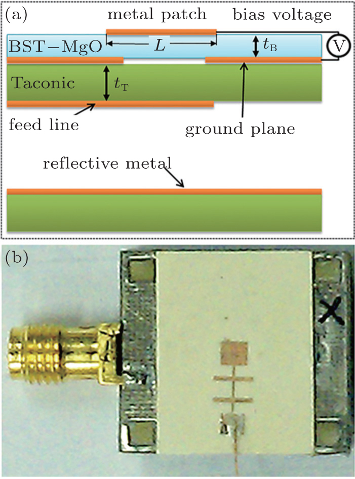
The schematic and prototype of designed FRC antenna are shown in Fig. 1. Taking into account the electromagnetic parameters of Taconic laminates and BST– MgO ceramic slices, the high frequency structure simulation (HFSS) software is adopted to simulate the structure of FRC antenna at a central frequency of 9 GHz and zero bias E-field. It should be mentioned that a filter was inserted between the metal patch and DC bias electrode [see Fig. 1(b)] for eliminating the interference between them. The detailed design of a similar FRC antenna has been published in our earlier work.[17]
Fig. 1. (a) Side view of the schematic FRC antenna with a BST– MgO of tB = 0.3 mm and Taconic of tT = 1 mm in thickness; (b) the prototype of the designed FRC aperture-coupled microstrip antenna.
The x-ray diffraction (XRD) and scanning electron microscopy (SEM) were employed to analyze the structure and composition of the BST– MgO ceramics. The ferroelectric properties were measured by RT Premier II ferroelectric tester. The dielectric constant and dielectric loss at microwave frequency were measured by an open cavity method using Agilent N5224A network analyzer. Open cavity based on resonance is one of most precise methods of measuring dielectric materials at rf/microwave frequencies. This method is able to measure permittivity as high as 2000, and its measurement precision of dielectric loss tan δ is less than 1%. However, this method also has its drawbacks: it cannot give a continuous spectrum measurement, only the cylindrical samples, which are processed into special D/H ratios, such as D/H = 1.0 ∼ 1.3, 1.9 ∼ 2.3, and 3.0 ∼ 3.3, can be used to measure their ɛ r and tan δ values, which are shown in Table 1.
Table 1.
Table 1.
Table 1. Frequency-dependences of microwave dielectric properties of BST– MgO ceramic composites with various sample dimensions (D: diameter, H: height).
Materials
D/mm
H/mm
f0/GHz
ɛ r
tan δ /10− 3
11.19
6.08
1.990
322
3.33
BST– MgO
4.68
3.89
6.437
117
5.07
4.93
2.34
9.510
85
11.96
BST
9.82
8.12
0.86
1602
6.43
Table 1. Frequency-dependences of microwave dielectric properties of BST– MgO ceramic composites with various sample dimensions (D: diameter, H: height).
3.Results and discussion
The XRD pattern of BST– MgO slice is shown in Fig. 2. As illustrated, the composite is composed of BST and MgO, and no additional phase is observed. Figure 3 shows the SEM backscattering electron image of BST– MgO slice. As illustrated, the BST and MgO phases are white and dark respectively due to their different yields of backscattered electrons. The BST grains are uniformly separated by MgO grains without aggregation. This microstructure of BST– MgO ceramic is favorable for the reduction of dielectric loss.
Fig. 3. FE-SEM BEI images of BST– MgO ceramic slices.
Figure 4(a) shows a fairly low leakage current density less than 8 nA/cm2 at 500 Hz under a DC bias of 2.5 kV. As there is a linear relationship between the dielectric constant ɛ r and the capacitance from the C– V curve shown in Fig. 4(b) the electric field tunability of ɛ r can be calculated by using the following equation:
Here, C(0) is the capacitance at the zero bias field, and C(E) is the capacitance at the DC bias field of E. As illustrated in Fig. 4(b), the calculated tunability is about 14.8% with the DC bias voltage ranges from 0 to 2.5 kV (i.e. the DC bias E-field from 0 to 8.33 kV/cm).
Fig. 4. (a) Current leakage at 500 Hz and (b) C– V curve for the BST– MgO composite.
The frequency dependences of the dielectric constant ɛ r and dielectric loss tan δ of BST– MgO and BST ceramics are summarized in Table 1. It should be mentioned here that owing to the special characteristics of open cavity described in Section 2, we are only able to obtain some discrete experimental values of ɛ r and tan δ at cavity resonance frequency f0 for the samples with special D/H ratios, rather than continuous frequency spectra. As shown in Table 1, the pure BST exhibits very large ɛ r of (1602), moreover its tan δ is as high as 6.43 × 10− 3 even at a low frequency of 0.86 GHz. As is well known, tan δ will rapidly increase with frequency increasing. Thus, the pure BST is not suitable for antenna material due to its high ɛ r and large tan δ . However, the BST– MgO composite ceramic has a moderate ɛ r of 85 and lower tan δ of 0.01 at 9.5 GHz, indicating an ideal antenna material. Based on the dielectric properties of BST– MgO, the FRC antenna is simulated by using the dielectric constants of 85 for BST– MgO slice and 2.55 for Taconic slice (see Fig. 1), and the central frequency of 9 GHz. When a DC bias voltage is applied between the metal patch and the ground plane (Fig. 1(a)), the relative dielectric constant of BST– MgO ceramic slice will be reduced.
Assuming that the BST– MgO composite substrate is isotropic, the resonance frequency of the dominant TM10 mode in BST substrate can be expressed as
where L is the width of the square radiation patch (Fig. 1(a)). According to Eq. (2), the central frequency of FRC antenna will be moved to a higher frequency when ɛ r decreases with applying an increasing DC voltage. In other words, the FRC antenna can be manipulated by the bias E-field. This frequency shift can be directly observed by detecting the return loss. Figure 5 shows the E-field dependence of measured return loss for the designed BST– MgO FRC antenna. As illustrated, the central frequency of FRC antenna is shifted from 9.1 GHz to 10.1 GHz with a considerably large frequency increment of 1000 MHz as the bias E-field increases from 0 to 8.33 kV/cm, equivalent to an ultrahigh antenna tuning efficiency Δ f/Δ E of 1.2 × 10⁵ Hz· cm/V. This indicates that a continuous reconfiguration of central frequency with an ultrahigh tunability of 11.0% is achieved by use of BST– MgO ceramic slices via the E-field manipulation.
Fig. 5. The E-field dependences of return loss for the designed BST– MgO FRC antenna.
Figure 6 shows the E-field and frequency dependences of radiation patterns. As illustrated, relatively large central gains of more than 7.5 dB are obtained at E-fields from 0 to 8.33 kV/cm and the frequencies from 9.1 GHz to 10.1 GHz. Figure 6 also reveals that the radiation patterns maintain the same shape at different tuning bias E-fields, and the main radiation direction keeps essentially unchanged in both E and H planes. This feature is very conducive to the practical application for the FRC antennas.
Fig. 6. The E-field and frequency dependences of radiation patterns of (a) E plane and (b) H plane. The black square (■ ) refers to 0 kV/cm@9.1 GHz, the red circle (● ) 5.0 kV/cm@9.6 GHz, the blue triangle (▲ ) 6.67 kV/cm@9.9 GHz, and the dark-cyan pentagram (★ ) 8.33 kV/cm@10.1 GHz.
4.Conclusions
The 45.0 wt% (Ba0.5Sr0.5)TiO3– 55.0 wt% MgO composite ceramic is sintered at 1380 ° C× 3 h. It is revealed that the BST– MgO composite is suitable to fabricate the frequency reconfigurable antenna due to its good high-frequency dielectric performances, such as an appropriate dielectric constant ɛ r (85), lower dielectric loss tan δ (0.01) around 9.0 GHz, and large tunability of ɛ r (14.8%) at an E-field of 8.33 kV/cm. A considerably large frequency shift (1000 MHz) with an ultrahigh central frequency tunability of 11.0% at a bias E-field of 8.33 kV/cm (equivalent to an ultrahigh antenna tuning efficiency of 1.2 × 10⁵ Hz· cm/V) and a large gain (more than 7.5 dB) are obtained in the designed aperture-coupled microstrip antenna. These results demonstrate that BST– MgO composite ceramic as an antenna medium is promising to fabricate E-field tunable frequency reconfigurable antenna.
SchaubertD H, FarrarF G, HayesS T and SindorisA R1983Frequency-agile, polarization diverse microstrip antennas and frequency scanned arrays [P]US 06/175543[Cited within:1]
... [1] Among such devices, the frequency reconfigurable (FRC) antennas, whose concept was first raised in 1983,[2] became a potential candidate for improving the channel capacity (or frequency agility) ...
1
1983
0.0
0.0
... [1] Among such devices, the frequency reconfigurable (FRC) antennas, whose concept was first raised in 1983,[2] became a potential candidate for improving the channel capacity (or frequency agility) ...
1
2010
0.0
0.0
... Barium strontium titanate (BST) is a promising ferroelectric material for RFC antenna due to its excellent microwave characteristics,[3] such as electric-field tunable permittivity and relatively low dielectric loss ...
1
2000
0.0
0.0
... [4] BST also shows great prospective in some tunable microwave components, such as phase shifter,[5] tunable filter,[6] varactor,[7] delay line,[8] etc ...
1
2012
0.0
0.0
... [4] BST also shows great prospective in some tunable microwave components, such as phase shifter,[5] tunable filter,[6] varactor,[7] delay line,[8] etc ...
2
2005
0.0
0.0
... [4] BST also shows great prospective in some tunable microwave components, such as phase shifter,[5] tunable filter,[6] varactor,[7] delay line,[8] etc ...
... 800),[6,9] however, the preparation methods, such as pulsed laser deposition, magnetron sputtering and metalorganic chemical vapor deposition, are too expensive to be used in the microwave industry ...
1
2008
0.0
0.0
... [4] BST also shows great prospective in some tunable microwave components, such as phase shifter,[5] tunable filter,[6] varactor,[7] delay line,[8] etc ...
1
2005
0.0
0.0
... [4] BST also shows great prospective in some tunable microwave components, such as phase shifter,[5] tunable filter,[6] varactor,[7] delay line,[8] etc ...
1
2012
0.0
0.0
... 800),[6,9] however, the preparation methods, such as pulsed laser deposition, magnetron sputtering and metalorganic chemical vapor deposition, are too expensive to be used in the microwave industry ...
1
1999
0.0
0.0
... [10#cod#x2013 ...
1
2004
0.0
0.0
1
2003
0.0
0.0
... 12] ...
1
2006
0.0
0.0
... [13#cod#x2013 ...
1
2009
0.0
0.0
1
2013
0.0
0.0
1
2012
0.0
0.0
... 16] In this paper, a composite ceramic with a composition of 45#cod#x00A0 ...
1
2015
0.0
0.0
... [17] ...
Ultrahigh frequency tunability of aperture-coupled microstrip antenna via electric-field tunable BST
[Du Hong-Leia), Xue Qiana), Gao Xiao-Yanga), Yao Feng-Ruia), Lu Shi-Yanga), Wang Ye-Longb), Liu Chun-Hengc), Zhang Yong-Chenga), Lü Yue-Guangb), Li Shan-Dong†a),d)]


 ]
]