


Study of hysteresis behavior in reactive sputtering of cylindrical magnetron plasma
[Kakati H.a) , Borah S. M.†b)  ]
]
]
|
|


†Corresponding author. E-mail: sankarmoni@gmail.com
*Project supported by the Department of Science and Technology, Government of India and Council of Scientific and Industrial Research, India.
In order to make sufficient use of reactive cylindrical magnetron plasma for depositing compound thin films, it is necessary to characterize the hysteresis behavior of the discharge. Cylindrical magnetron plasmas with different targets namely titanium and aluminium are studied in an argon/oxygen and an argon/nitrogen gas environment respectively. The aluminium and titanium emission lines are observed at different flows of reactive gases. The emission intensity is found to decrease with the increase of the reactive gas flow rate. The hysteresis behavior of reactive cylindrical magnetron plasma is studied by determining the variation of discharge voltage with increasing and then reducing the flow rate of reactive gas, while keeping the discharge current constant at 100 mA. Distinct hysteresis is found to be formed for the aluminium target and reactive gas oxygen. For aluminium/nitrogen, titanium/oxygen and titanium/nitrogen, there is also an indication of the formation of hysteresis; however, the characteristics of variation from metallic to reactive mode are different in different cases. The hysteresis behaviors are different for aluminium and titanium targets with the oxygen and nitrogen reactive gases, signifying the difference in reactivity between them. The effects of the argon flow rate and magnetic field on the hysteresis are studied and explained.
The technique of reactive magnetron sputtering is used to deposit compound thin films of different metals such as metal nitrides[1– 3] and metal oxides.[4– 8] In this technique for compound thin film deposition, generally a metallic target is sputtered in an environment of inert gas or reactive gas. The process of reactive sputtering can be very complex and involves a) the sputtering process, b) the physics of the plasma discharge, c) transport of the sputtered and gas species, d) the kinetics of film growth, and e) chemical interactions at the target and film surfaces. The reactive sputtering can be operated in different modes such as metallic, transition and reactive mode.[9] These modes are extremely sensitive to the supply of the reactive gas. It is important to have very good control of these processes for proper deposition of the thin film. In the metallic mode, the sputtering rate of the target will be high but it will lead to under-stoichiometric composition of the deposited film. A very high supply of the reactive gas enables stoichiometric deposition but it also leads to the poisoning of the target, which lowers both the sputtering and the deposition rate. Therefore, the optimum deposition condition is that when both a high deposition rate and stoichiometric film can be grown.[10]
The magnetron sputtering of titanium and aluminium target in a reactive environment of argon, oxygen and nitrogen gases is used for depositing titanium nitride, and titanium oxide films, aluminium nitride and aluminium oxide films respectively. Each of these films has its own importance for different types of coatings. Titanium nitride (TiN) is a suitable candidate for industrial applications because of its unique properties like high hardness, good wear and corrosion resistance.[11– 13] It also has good electrical, thermal, mechanical and chemical properties. Similarly, titanium dioxide (TiO2) has many excellent physical properties such as a high dielectric constant, strong mechanical and chemical stability as well as good insulating properties. Again, aluminium oxide thin films are widely used in different industrial applications from microelectronic and optical applications to wear resistant coatings.[14– 21] Aluminum nitride (AlN) has attracted a great deal of attention in several fields of new technology, because of its outstanding properties, such as a wide band gap (∼ 6.2 eV), high thermal conductivity, thermal and chemical stability and high acoustic wave velocity with fairly good piezoelectricity.[22, 23]
The transition of the discharge from one mode to another often leads to a hysteresis effect depending on the reactivity between the target and the reactive gas as well as on different process parameters. During the transition of the discharge from metallic to reactive mode, the partial pressure of the reactive gas becomes high in the poisoned mode. As the transition of the discharge takes place from the reactive mode to the metallic mode, the partial pressure of the reactive gas still remains higher in the transition region, resulting in the formation of hysteresis. Therefore, the consumption of more reactive gases takes place in the hysteresis region when the transition takes place from the metallic to the reactive mode.[24] For effective deposition of compound thin film, these characteristics need to be studied. The cylindrical magnetron sputtering system has the ability to uniformly coat a large area of the substrate by appropriately changing the magnetic field. Unlike a planar magnetron, in cylindrical magnetron plasma the sputtering and compound formation over the whole metallic target surface are effective and uniform and the racetrack effect is eliminated. In the present work, we study the hysteresis behaviors in cylindrical magnetron plasma for different targets namely aluminium and titanium with oxygen and nitrogen as reactive gases.
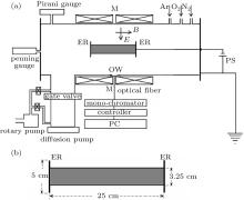
The detailed description about the cylindrical magnetron device used in this experiment is available in some recent publications of our group.[13, 25– 29] Briefly the device contains a stainless steel cylindrical chamber having dimensions of 30 cm in diameter and 100 cm in length. A small titanium or aluminium cylinder is placed co-axially inside the chamber, which acts as a cathode. The length of the cathode is 25 cm and its outer diameter is 3.25 cm. Both ends of the cathode are terminated by stainless steel end reflectors of 5 cm in diameter. For generating the steady axial magnetic field, two coils each having 1500 turns, of enamel-coated copper wire are placed around the body of the chamber. Direct current from a DC power supply (150 V, 50 A) passes through both the coils to produce an axial magnetic field parallel to the cathode surface. The coils produce a magnetic field of 2.5 Gs (1 Gs = 10– 4 T) per ampere of DC current passing through it. The magnetic field is measured with the help of a Hall probe and found to be uniform within a length of ∼ 40 cm at the central portion of the chamber. The radial variation of the magnetic field is within 5%. The schematic diagram of the experimental set-up is shown in Fig. 1.
 | Fig. 1. (a) Schematic diagram of the experimental set up. MM: magnetic field coils, B: magnetic field, E: electric field, PS: discharge power supply, ER: end reflectors, QW: quartz window; (b) schematic diagram of the titanium/aluminium target. |
The vacuum unit consists of a rotary pump having a displacement rating of 350 lt/min and a diffusion pump with an effective pumping speed of 700 lt/s. The base pressure of the chamber is brought down ∼ 2× 10– 6 Torr (1 Torr = 1.33322 × 10² Pa). The partial pressure with the working gas mixture is maintained in a range of ∼ 10– 3 Torr– 10– 2 Torr. Argon, oxygen, and nitrogen gases are injected separately into the chamber through mass flow controllers (Aalborg, USA). The discharge power is supplied from a stabilized DC power supply (1500 V, 5 A) working in the voltage-regulated mode. Plasma is produced by applying a DC voltage (350 V– 750 V) across a cylindrical titanium/aluminium electrode as the cathode and the grounded chamber as the anode. The axial magnetic field applied is 50 Gs– 150 Gs. Plasma parameters are measured with a cylindrical Langmuir probe made of tungsten having diameter 0.05 cm and length 0.5 cm. Typical measured plasma parameters are plasma density, ‘ ne’ ∼ (109– 1010) cm– 3 and electron temperature, ‘ Te’ ∼ (0.5– 5) eV.
The optical emission spectra of discharge are recorded using a BENTHAM M300 Monochromator through optical fibre cable. The focal length of the monochromator is 30 cm and it is coupled with a photomultiplier tube (PMT) and a programmable motor controller. The output signal from the PMT is transferred to a personal computer (PC) through an analog-to-digital converter.
Figure 2(a) shows the optical emission spectrum in a range of 390 nm– 404 nm, which contains the Al emission line at wavelength 396.1 nm recorded during sputtering of the Al target at an argon flow rate of 15 sccm, discharge current 100 mA and magnetic field 100 Gs. Figure 2(b) shows the optical emission spectrum in a wavelength range of 455 nm– 480 nm containing the titanium emission line (466.7 nm) recorded during sputtering of the titanium target at an argon flow rate of 15 sccm, discharge current 100 mA and magnetic field 100 Gs. These two lines are considered to be resonant lines to the ground state and their intensities can be considered as a representative of the density of that particular species in the plasma.
 | Fig. 2. OES spectra showing (a) Al line, (b) Ti line. |
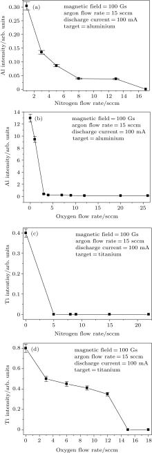
Figure 3(a) shows the variation of emission intensity of aluminium with the increase in nitrogen flow rate at an argon flow rate of 15 sccm, magnetic field 100 Gs and discharge current 100 mA. The aluminium intensity decreases to almost a minimum value at a nitrogen flow rate of 8 sccm. This indicates that after about 8 sccm of the nitrogen flow rate, the aluminium target turns reactive and the aluminium emission intensity reduces significantly.
 | Fig. 3. Intensity of (a) Al at different nitrogen flow rates, (b) Al at different oxygen flow rates, (c) Ti at different nitrogen flow rates, and (d) Ti at different oxygen flow rates. |
Figure 3(b) shows the variation of emission intensity of aluminium with the increase in oxygen flow rate at an argon flow rate of 15 sccm, magnetic field 100 Gs and discharge current 100 mA. Unlike Fig. 3(a), the emission intensity of alumium decreases very rapidly with an increase in the oxygen flow rate and becomes minimum at about oxygen flow rate 3 sccm. This signifies that under the discharge conditions, 3 sccm of oxygen flow rate converts the target into the poisoned mode. It can be realised from these figures that the oxygen gas is more reactive than nitrogen to aluminium. Therefore, the reactive mode for an aluminium target is reached at a lower oxygen flow rate than the nitrogen flow rate.
Figure 3(c) shows the variation of titanium emission intensity with an increase in the nitrogen flow rate. It should be mentioned here that with the increase in the nitrogen flow rate, the targeted titanium line is dominated by the nitrogen line (464.3 nm) near to that peak. Therefore, after 5 sccm of the nitrogen flow rate, it becomes impossible to determine the titanium emission intensity as the titanium emission line is completely overlapped by the nitrogen emission line and therefore, the emission intensity of titanium is shown to be zero.
Figure 3(d) shows the variation of titanium emission intensity with the increase in the oxygen flow rate at an argon flow rate of 15 sccm, magnetic field 100 Gs and discharge current 100 mA. It is seen that titanium emission intensity decreases gradually with the increase of the oxygen flow rate. In comparison to the aluminium target, the emission intensity of titanium decreases gradually with the increase of the oxygen flow rate, which means that oxygen gas is less reactive to the titanium target than to the aluminium target.
Figure 4(a) shows the variations of the discharge voltage with the nitrogen flow rate for an aluminium target at magnetic field 100 Gs, argon flow rate 10 sccm and discharge current 100 mA. The discharge voltage, while keeping the discharge current constant at 100 mA, decreases at a rapid rate up to about 10 sccm and then it decreases gradually with the increasing of the nitrogen flow rate. This indicates that after about 10 sccm of the nitrogen flow rate, the target becomes reactive. This observation closely resembles that found from optical emission spectroscopy analysis. Owing to there being less reactivity of nitrogen, the partial pressure of nitrogen increases proportionally with the increase of the nitrogen flow rate. As the target becomes slowly reactive, the partial pressure of nitrogen gas becomes high with the increase of the nitrogen flow rate, which leads to the increase of the discharge current at the same discharge voltage. Therefore, to maintain the same discharge current, a smaller discharge voltage is required. After reaching the poisoned mode, the discharge voltage decreases slowly with the further increase of nitrogen flow rate. When the nitrogen flow rate decreases, the discharge voltage increases almost in the same manner, but with a lower value in the transition region than when it increases. This leads to the formation of the hysteresis. During the decrease of the nitrogen flow rate, the partial pressure of the reactive gas remains high in the hysteresis region and so smaller discharge voltage is required to maintain the same discharge current.
 | Fig. 4. Changes of discharge voltage with nitrogen flow rate for aluminium target at discharge current 100 mA and (a) magnetic field 100 Gs and argon flow rate 10 sccm, (b) magnetic field 100 Gs and argon flow rate 15 sccm, (c) magnetic field 100 Gs and argon flow rate 20 sccm, (d) argon flow rate 15 sccm and magnetic field 50 Gs, and (e) argon flow rate 15 sccm and magnetic field 150 Gs. |
Figures 4(b) and 4(c) show the variations of the discharge voltage with the nitrogen flow rate for an aluminium target at magnetic field 100 Gs, discharge current 100 mA and argon flow rates 15 sccm and 20 sccm respectively. For all the argon flow rates 10 sccm, 15 sccm, and 20 sccm, with the other parameters fixed, the discharge voltage for an aluminium target varies almost identically with the increasing and decreasing of the nitrogen flow rate. The reactive mode of the target in each case starts almost at a nitrogen flow rate of 10 sccm. This means that the variation of the discharge voltage with the nitrogen flow rate is almost independent of the argon flow rates in these investigations for an aluminium target.
Figure 4(d) represents the variations of the discharge voltage with the nitrogen flow rate at magnetic field 50 Gs, argon flow rate 15 sccm and discharge current 100 mA for an aluminium target. The discharge voltage is found to decrease proportionally with the increase of the nitrogen flow rate up to 5 sccm. This is because, in the present case, there is less trapping of the charged particles around the cathode at such a low magnetic field and the sputtering is effective in preventing the target from converting completely into the reactive mode up to a high value of the nitrogen flow rate. It is evident from the figure that at lower magnetic field, 50 Gs, the target remains in the transition region up to a very high flow rate of the nitrogen gas. Since at a lower magnetic field, the trapping of the charged particles is not effective, so, a high discharge voltage is required to maintain the same discharge current as seen from the figure. Sputtering at high voltage (high ion energy) reduces the chance of nitride formation on the target surface. This signifies that the sputtering of the aluminium target remains effective at the lower magnetic field at a high nitrogen flow rate, and this prevents the transition of the discharge from converting into a reactive mode up to a high value of the nitrogen flow rate. This in turn means that a higher magnetic field leads to the trapping of charged particles including nitrogen ions near the target, which leads to the appearance of a reactive mode at the lower nitrogen flow rate.
Figure 4(e) shows the variations of discharge voltage with nitrogen flow rate at magnetic field 150 Gs, argon flow rate 15 sccm and discharge current 100 mA for an aluminium target. The appearance of hysteresis behavior is found to be prominent at this magnetic field. In this case, the reactive mode appears at a nitrogen flow rate of about 8 sccm. This signifies that the transition of one mode to another is effectively influenced by trapping the ionized reactive gas with using the magnetic field, the discharge voltage and discharge current. At a higher magnetic field, the trapping of the charged particles is effective near the target and so a smaller discharge voltage is required to maintain the same discharge current. Owing to less cathode voltage and trapping of charged particles near the target, the compound formation on the target is enhanced at a comparatively low nitrogen flow rate.
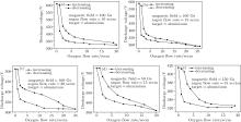
Figures 5(a), 5(b), and 5(c) represent the changes of discharge voltage with oxygen flow rate for an aluminium target at magnetic field 100 Gs, discharge current 100 mA and argon flow rates 10, 15, and 20 sccm. For each case, the discharge voltage almost remains constant up to an oxygen flow of 2 sccm after which it decreases sharply and after about 4 sccm of oxygen flow rate the discharge voltage becomes almost minimum. This means that up to 2 sccm– 3 sccm of oxygen flow rate, the target remains in metallic mode and at an about 4 sccm of oxygen flow rate, the target becomes reactive. In comparison to the case of nitrogen gas, the reactive mode occurs at a lower oxygen flow rate. This represents a higher reactivity of oxygen gas than that of the nitrogen to aluminium. In the metallic region, oxygen gas consumption for compound formation with aluminium is effective and so partial pressure of oxygen gas does not increase. Therefore, in the metallic region, the discharge voltage does not change much with the increase of the oxygen flow rate unlike the nitrogen/aluminium case. The hysteresis behaviors are observed at all the argon flow rates of 10, 15, and 20 sccm, and not much change in the pattern of the discharge voltage variation with the increase or decrease of oxygen flow rate is observed.
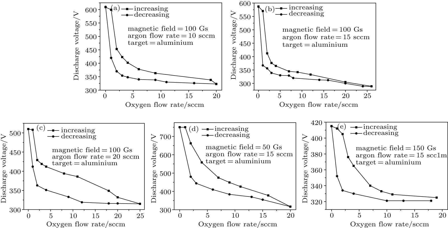 | Fig. 5. Changes of discharge voltage with oxygen flow rate for aluminium target at discharge current 100 mA and (a) magnetic field 100 Gs and argon flow rate 10 sccm, (b) magnetic field 100 Gs and argon flow rate of 15 sccm, (c) magnetic field 100 Gs and argon flow rate 20 sccm, (d) argon flow rate 15 sccm and magnetic field 50 Gs, and (e) argon flow rate 15 sccm and magnetic field 150 Gs. |
Figures 5(d) and 5(e) show the variations of discharge voltage with the change in oxygen flow rate at argon flow rate 15 sccm, discharge current 100 mA and magnetic fields 50 Gs and 150 Gs respectively for an Al target. Almost similar variations of discharge voltage with a change in the oxygen flow rate are observed at all the magnetic fields. The hysteresis behavior has been found to be prominent at a higher magnetic field (150 Gs). With the increase of the magnetic field, the cathode voltage decreases and oxygen ions are effectively trapped near the target. This increases the chance for compound formation on the target and therefore, the hysteresis becomes more prominent.
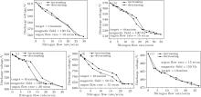
Figures 6(a)– 6(c) represent the changes of discharge voltage with the change of nitrogen flow rate for a titanium target at magnetic field 100 Gs, discharge current 100 mA and argon flow rates 10, 15, and 20 sccm respectively. At an argon flow rate of 10 sccm, the discharge voltage varies almost along a straight line with the increase and decrease of the nitrogen flow rate. However, when the argon flow rate is raised to 15 sccm, the discharge voltage decreases sharply as the nitrogen flow rate increases from 15 sccm to 23 sccm, after which it again decreases gradually. This means that as the argon flow rate increases, there is an abrupt change of the target from the metallic to the reactive mode at the nitrogen flow rate of 15 sccm. At an argon flow rate of 20 sccm, the discharge voltage decreases gradually down to that at a nitrogen flow rate of 12 sccm. It then decreases sharply down to that at a nitrogen flow rate of 17 sccm and after that, again the discharge voltage decreases gradually. The hysteresis behavior is not prominent unlike for an aluminium target, indicating less reactivity between nitrogen and titanium than between nitrogen and aluminium. However, at 20 sccm of argon flow rate, there is an indication of the formation of the hysteresis. This is because at a higher argon flow rate, the discharge with more sputtering argon ions prevents the target from converting into the reactive or the transition mode. At a higher argon flow rate of 20 sccm, the sputtering rate is higher and therefore, the gas consumption of the reactive gas is higher in the metallic mode. Therefore, at a higher argon flow rate, the transition of the discharge from the metallic to the reactive mode is steep and the hysteresis is formed.
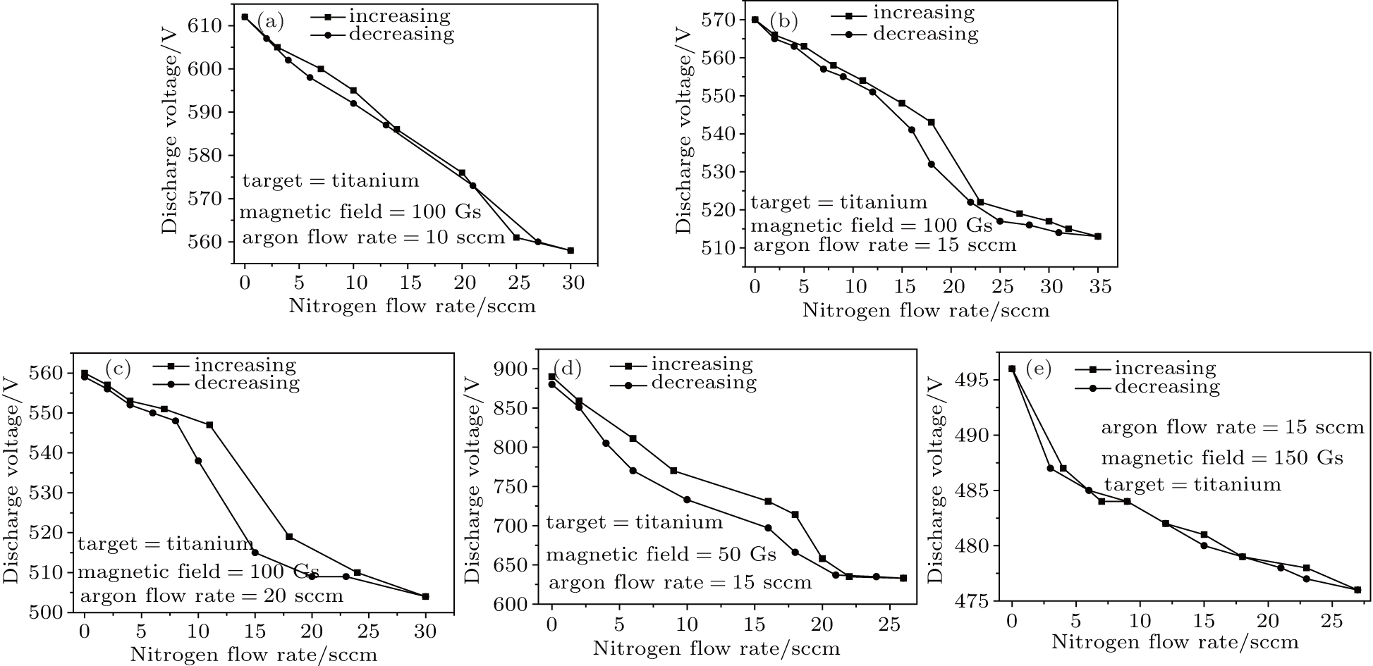 | Fig. 6. Changes of discharge voltage with nitrogen flow rate for titanium target at discharge current 100 mA and (a) magnetic field 100 Gs and argon flow rate 10 sccm, (b) magnetic field 100 Gs and argon flow rate 15 sccm, (c) magnetic field 100 Gs and argon flow rate 20 sccm, (d) argon flow rate 15 sccm and magnetic field 50 Gs, and (e) argon flow rate 15 sccm and magnetic field 150 Gs. |
Figures 6(d) and 6(e) show the changes in discharge voltage with the change of the nitrogen flow rate at argon flow rate 15 sccm, discharge current 100 mA and magnetic fields 50 Gs and 150 Gs respectively for a titanium target. At a magnetic field of 50 Gs, there is an indication of the formation of hysteresis, however at 150 Gs, there is no formation of hysteresis. This is because at the lower magnetic field, the target can remain metallic up to a high value of nitrogen flow rate. As the reactivity between the titanium and nitrogen is low, the reactive mode appears at the higher nitrogen flow rate. Therefore, when the nitrogen flow rate is reduced the hysteresis appears. However, at magnetic field 150 Gs, the sputtering rate lowers and balancing between the sputtering and nitride formation on the target surface causes the hysteresis to disappear. This represents that the dependence of hysteresis behavior on the magnetic field is also dependent on the reactivity between the metallic target and reactive gas.
Figures 7(a)– 7(c) show the changes in the discharge voltage with the change in oxygen flow rate at magnetic field 100 Gs for a titanium target with keeping the discharge current at 100 mA while changing argon flow rates at 10, 15, and 20 sccm respectively. These figures show the occurrence of the hysteresis, and the hysteresis is more prominent at the higher argon flow rate. As the argon flow rate increases, the sputtering rate is higher and it leads to more reactive gas consumption in the metallic mode. Thus, it prevents the target from converting into the reactive mode up to a high value of the oxygen flow rate. After reaching the reactive mode, when the oxygen flow rate is reduced, the discharge voltage has become a lower value. Owing to this reason, hysteresis occurs in the voltage– flow rate characteristics. The hysteresis behavior is found to be more prominent at higher argon flow rates 15 sccm and 20 sccm. The poisoned mode of the target occurs at about an oxygen flow rate of 18 sccm. The poisoning mode occurs at higher oxygen flow rates unlike for an aluminium target where the target becomes oxidized at a lower oxygen flow rate. This represents less reactivity of oxygen to the titanium target than to the aluminium target.
 | Fig. 7. Changes of discharge voltage with nitrogen flow rate for aluminium target at discharge current 100 mA and (a) magnetic field 100 Gs and argon flow rate 10 sccm, (b) magnetic field 100 Gs and argon flow rate 15 sccm, (c) magnetic field 100 Gs and argon flow rate 20 sccm, (d) argon flow rate 15 sccm and magnetic field 50 Gs, and (e) argon flow rate 15 sccm and magnetic field 150 Gs. |
Figures 7(d) and 7(e) show the changes in the discharge voltages with the oxygen flow rate for a titanium target at discharge current 100 mA, argon flow rate 15 sccm and magnetic fields 50 Gs and 150 Gs respectively. The hystereses are found to occur in both cases. Comparing the hysteresis behaviors for a titanium target in a nitrogen environment and an oxygen environment, it can be concluded that oxygen gas is more reactive to a titanium target than nitrogen.
The hysteresis phenomena for reactive cylindrical magnetron discharge are studied. The hysteresis width and its occurrence are found to be dependent on the reactivity between the reactive gas and the metallic target. The hysteresis behaviors of the discharge for aluminium and the titanium targets are more prominent for oxygen gas than for nitrogen gas, which indicates that oxygen gas is more reactive to these targets. Similarly, it is seen that the hysteresis is more prominent for an aluminium target than for a titanium target for both oxygen and nitrogen gases. In the reactive mode, the reactive gas consumption for the compound formation is lower due to the reduced sputtering rate and therefore, partial pressure of the reactive gas increases, which leads to the increase of the discharge current. Therefore, a smaller discharge voltage is required to maintain the same discharge current in the reactive mode of the discharge. At a higher argon flow rate, the hysteresis is found to be more prominent and the target remains metallic up to a high value of the reactive gas flow rate. This is because at the higher argon flow rate, the reactive gas has less chance to react with the target and the sputtering is also effective. Therefore, in order to achieve a high value of the reactive gas flow rate, the target still remains metallic. It is seen that at a higher magnetic field, the hysteresis is more prominent and the reactive mode occurs at a lower pressure of the reactive gas flow rate. This is due to the fact that at a higher magnetic field, the charged particles are effectively confined near the target by the higher magnetic field and also a smaller cathode voltage is required to maintain the same discharge current.
The authors thank the research group of the Material Sciences Division, Institute of Advanced Study in Science and Technology (IASST), Guwahati for their help and support during the authors’ working tenure there.
| 1 |
|
| 2 |
|
| 3 |
|
| 4 |
|
| 5 |
|
| 6 |
|
| 7 |
|
| 8 |
|
| 9 |
|
| 10 |
|
| 11 |
|
| 12 |
|
| 13 |
|
| 14 |
|
| 15 |
|
| 16 |
|
| 17 |
|
| 18 |
|
| 19 |
|
| 20 |
|
| 21 |
|
| 22 |
|
| 23 |
|
| 24 |
|
| 25 |
|
| 26 |
|
| 27 |
|
| 28 |
|
| 29 |
|