
Entransy analyses of heat–work conversion systems with inner irreversible thermodynamic cycles
[Cheng Xue-Tao† , Liang Xin-Gang]
, Liang Xin-Gang]
|
|


†Corresponding author. E-mail: chengxt02@gmail.com
*Project supported by the National Natural Science Foundation of China (Grant Nos. 51376101 and 51356001).
In this paper, we try to use the entransy theory to analyze the heat–work conversion systems with inner irreversible thermodynamic cycles. First, the inner irreversible thermodynamic cycles are analyzed. The influences of different inner irreversible factors on entransy loss are discussed. We find that the concept of entransy loss can be used to analyze the inner irreversible thermodynamic cycles. Then, we analyze the common heat–work conversion systems with inner irreversible thermodynamic cycles. As an example, the heat–work conversion system in which the working fluid of the thermodynamic cycles is heated and cooled by streams is analyzed. Our analyses show that larger entransy loss leads to larger output work when the total heat flow from the high temperature heat source and the corresponding equivalent temperature are fixed. Some numerical cases are presented, and the results verify the theoretical analyses. On the other hand, it is also found that larger entransy loss does not always lead to larger output work when the preconditions are not satisfied.
The analysis of thermal systems is an important topic and has attracted more and more attention because of the worldwide energy crisis.[1– 4] For this topic, some theories have been developed. The entransy theory[1] is the latest one of them and has been widely used in thermal analyses and optimizations.[1, 5– 15]
The concept of entransy was proposed based on the analogy between heat and electrical conductions.[1] In the analogy, thermal energy corresponds to electrical charge, electrical potential corresponds to temperature, thermal resistance corresponds to electrical resistance, the Fourier’ s law for heat conduction corresponds to the Ohm’ s law, etc. Considering the fact that the thermal system lacks the parameter corresponding to the electrical potential energy, Guo et al.[1] proposed the concept of entransy. For an object, its electrical potential energy is half the product of the electrical charge and the electrical potential, while its entransy is half the product of the thermal energy and the temperature. In recent years, it was also found that the concept of entransy corresponds to the potential energy of thermomass.[16] In practical heat transfer processes, the system entransy always decreases, which means that entransy dissipation always exists.[1, 8, 17] Based on the concept of entransy dissipation, the principles of extremum entransy dissipation and minimum entransy-dissipation-based thermal resistance were proposed and applied to the analyses and optimizations of heat conduction, [1, 5– 7] heat convection, [1, 8] thermal radiation, [9, 18] heat exchangers, [10, 19] and heat exchanger networks.[20] The results showed that the entransy theory is effective for heat transfer analyses and optimizations.
Furthermore, the entransy theory was extended for the analyses and optimizations of heat– work conversion systems.[11– 15] The concept of entransy loss was proposed.[11] It is the difference between the entransy flows into and out of the discussed thermodynamic system, and the consumed entransy in the thermodynamic system. When some preconditions are satisfied, it was found that larger entransy loss leads to larger output work.[11– 13, 15, 21– 24] However, it was shown that there are some limitations to the application of the concept of entransy loss.[25] For instance, when the preconditions are not satisfied, larger entransy loss may not correspond to larger output work.[25] The entransy theory is not effective for the analyses of direct work processes.[25]
In the published papers, the discussed thermodynamic cycles are all endoreversible cycles. There are few reports on the application of the entransy theory to the analyses of inner irreversible thermodynamic cycles. In this paper, we try to use the entransy theory to analyze the heat– work conversion systems with inner irreversible thermodynamic cycles. The influences of different inner irreversible factors on entransy loss are analyzed. Some typical systems and numerical examples are investigated.
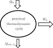
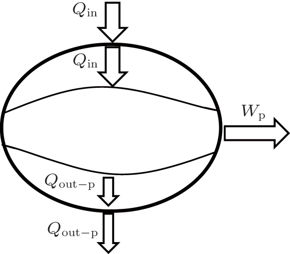
In the practical thermodynamic cycle shown in Fig. 1, the heat flow into the working fluid is Qin, while that out of the working fluid is Qout– p, and the output work is Wp. The first thermodynamic law gives

where

Here, qin and Ain are the heat flow density into the working fluid and the corresponding area, and qout– p and Aout are the heat flow density out of the working fluid and the corresponding area, respectively.
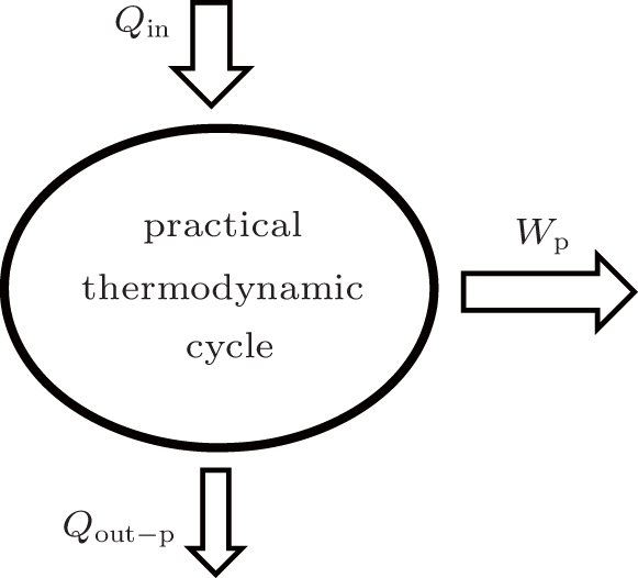 | Fig. 1. A practical thermodynamic cycle. |
In the cycle, there would be many inner irreversible factors, such as the heat leak, friction, throttling, flashing, mixing, etc., which can result in the loss of exergy and the decrease of the output work. Some examples will be discussed below.
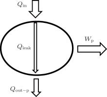
First, the inner irreversibility from the heat leak is discussed. As shown in Fig. 2, we assume that the heat leak between the inlet and outlet of heat flow is the only inner irreversible factor. As the heat leak is the only inner irreversible factor, the system shown in Fig. 2 can be treated as the sum of a heat transfer process and a reversible heat– work conversion process. The heat transfer process is the transfer of Qleak between the inlet and outlet of heat flow. In the reversible heat– work conversion process, the heat flow into the working fluid is Qin – Qleak, while that out of the working fluid is Qout– p – Qleak. From the viewpoint of entransy, there would be entransy dissipation in the heat transfer process, and the entransy loss is just the entransy dissipation, [26] i.e.,

where qleak is the heat leak density, and T is the corresponding temperature. For the reversible heat– work conversion process, the entransy loss is the work entransy,

Then, the whole entransy loss of the system is
where Gin is the entransy flow into the system, while Gout is that out of the system. It can also be seen that the entransy loss of the system is the difference between the entransy flows into and out of the system. With Eqs. (1) and (2), if we define the equivalent temperatures of the inlet and outlet of heat flow as

we can obtain
With fixing Qin, Tin, and Tout– p, larger entransy loss leads to larger output work. For this inner irreversible thermodynamic cycle, the relationship between the entransy loss and the output work can also be obtained. The concept of entransy loss can also be used in the analyses.
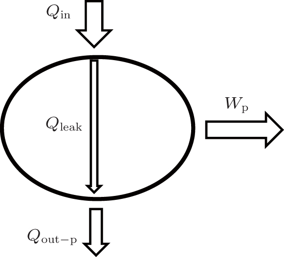 | Fig. 2. An inner irreversible cycle with heat leak. |
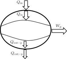
Second, we can discuss the irreversible cycle with inner heat transfer, which is shown in Fig. 3. In the cycle, we assume that some irreversible factors result in the temperature differences between the working fluid and the boundaries of the inlet and outlet of heat flow, then the inner heat transfer process happens. The thermodynamic cycle is composed of three parts, i.e., two heat transfer processes and a reversible heat– work conversion process. For the two heat transfer processes, the entransy losses are just the entransy dissipations,


where Af– in and Af– out are the corresponding areas through which the heat flow goes into and out of the working fluid, respectively. For the reversible heat– work conversion process, equation (4) indicates that the entransy loss is

Therefore, the sum of Eqs. (8), (9), and (10) gives the total entransy loss of the system. It can be shown that the entransy loss can also be expressed by Eq. (7), which means that the concept of entransy loss can also be applied to the analysis of this inner irreversible thermodynamic cycle.
 | Fig. 3. An irreversible cycle with inner heat transfer. |
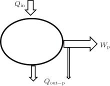
Third, as shown in Fig. 4, we discuss the inner irreversible thermodynamic cycle with friction. This system can be treated as the sum of a reversible heat– work process and a friction process. For the reversible heat– work conversion process, there is

where qout– c is the heat flow out of the system that results from the reversible cycle. When some of the output work is used to overcome friction, the work will turn into heat and goes out of the system at the outlet of heat flow. With this part of heat, some entransy flow also goes out of the system,

where qout– W is the heat flow density associated with the work. With Eqs. (11) and (12), we have
With Eq. (6), equation (7) can also be obtained. The concept of entransy loss can also be applied to the analysis of this inner irreversible thermodynamic cycle.
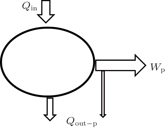 | Fig. 4. An inner irreversible cycle with friction. |
As shown above, the inner irreversibilities from the heat leak, friction, and heat transfer between the boundaries and the working fluid are mainly analyzed. It is shown that the relationships between the entransy loss and the output work can all be obtained for the discussed cases. Furthermore, in practical cycles, the discussed inner irreversibilities may exist at the same time, and there may be some other kinds of inner irrversibilities. If we analyze the irreversible factors respectively, their influences on the entransy loss may also be obtained. Then, the inner irreversible cycles may be analyzed with the entransy theory.
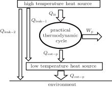
For the practical heat– work conversion system shown in Fig. 5, the heat flow into the heat engine, Qin, comes from the high temperature heat source, the heat flow out of the heat engine, Qout– p, enters the low temperature heat source, and there are heat leaks, Qleak– 1 and QLeak– 2, between the high and low temperature heat sources and between the high temperature heat source and the environment, respectively. The total heat flow into the low temperature heat source finally enters the environment. The output work of the system is Wp. As the inner irreversible thermodynamic cycle can be analyzed with the entransy theory, the whole system can be analyzed below.
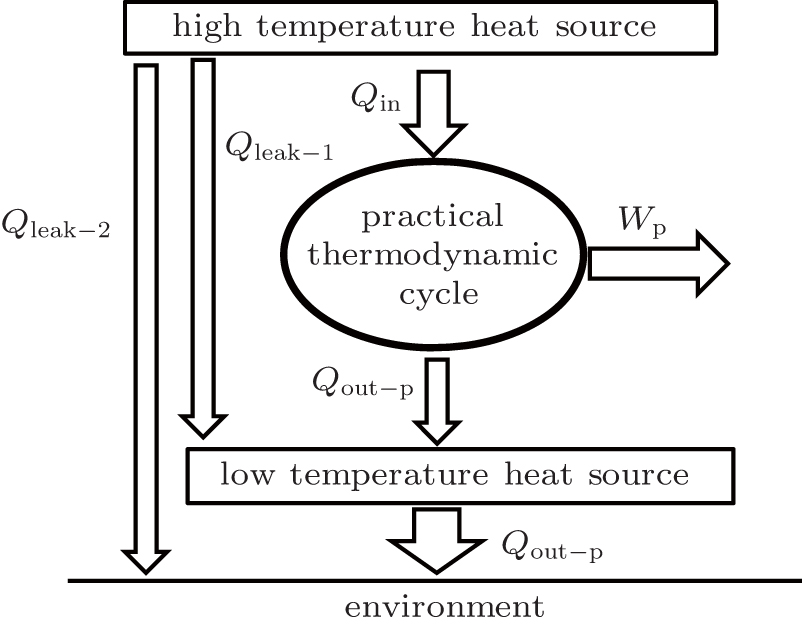 | Fig. 5. A heat– work conversion system with an inner irreversible thermodynamic cycle. |
For the cycle, the entransy loss can be expressed by Eq. (13). For the heat transfer process between the high temperature heat source and the heat engine, the heat transfer process between the heat engine and the environment, the heat transfer process between the low temperature heat source and the environment, and the heat leaks, the entransy losses are the entransy dissipations and are expressed as follows:


where qH is the heat flow density from the high temperature heat source, qL is the heat flow density into the low temperature heat source from the working medium, AH and AL are the corresponding heat transfer areas, qleak– 1 is the heat flow density of the heat leak between the high and low temperature heat sources, qleak– 2 is the heat flow density of the heat leak between the high temperature heat source and the environment, qout is the heat flow out of the low temperature heat source, and T0 is the environment temperature. Then, the total entransy loss of the system can be expressed by

Considering the energy conservation of the low temperature heat source, we can find that the second term on the right-hand side of Eq. (19) is zero. Then, we have
If we define the equivalent temperature of the high temperature heat source as
and consider the energy conservation, we can obtain

where the term in the first bracket is the total heat flow from the high temperature heat source. It can be seen that larger entransy loss leads to larger output work when the total heat flow from the high temperature heat source and the corresponding equivalent temperature are fixed. Based on Eq. (22), some specific cases are discussed below.
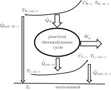
As shown in Fig. 6, we discuss the system in which the working fluid of the practical thermodynamic cycles is heated and cooled by streams. In the system, the heat capacity flow rate, inlet and outlet temperatures of the i-th hot stream are CH– i, TH– in– i, and TH– out– i respectively, while those of the i-th cold stream are CL– i, TL– in– i, and TL– out– i, respectively. The heat flow rate into the working fluid is Q̇ in, while that out of the working fluid is Q̇ out– p, and the output power is Ẇ p. As the used hot and cold streams are dumped into the environment at temperature T0, the heat leak rates between the used streams and the environment, Q̇ leak– H– i and Q̇ leak– L– i, should also be considered.
 | Fig. 6. A heat– work conversion system in which the working fluid is heated and cooled by streams. |
As entransy is half the product of the thermal energy and the temperature, the entransy flow rate should be half the product of the heat flow rate and the temperature. Therefore, the entransy flow rate into the system with the 

while that into the i-th cold stream is

As the used streams are dumped into the environment, the temperatures of the streams finally all reach T0. So, the entransy dissipation rates of the heat leak rates are

Considering Eqs. (20) and (22), we have
where n is the number of hot or cold streams. It can be seen that a larger entransy loss rate leads to a larger output power for fixed CH– i, TH– in– i, CL– i, and TL– in– i. When CH– i, TH– in– i, CL– i, and TL– in– i are given, the total heat flow and entransy flow from the streams are both fixed because all the temperatures of the streams finally equal that of the environment. Therefore, in Eq. (22), the preconditions with which larger entransy loss leads to larger output work are satisfied. This is the reason why larger entransy loss rate leads to larger output power for fixed CH– i, TH– in– i, CL– i, and TL– in– i in the discussed system shown in Fig. 6.
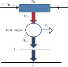
As a specific numerical example, we can calculate the system shown in Fig. 7, where there is only one hot stream whose heat capacity flow rate, C, is 5 W/K and inlet temperature, TH– in, is 600 K. The heat flow rate Q̇ in enters the heat engine through a heat exchanger whose wall temperature is TH, 540 K. The heat engine works between temperatures TH and TL, and releases the heat flow rate Q̇ out to the environment at temperature T0, 300 K. In the heat engine, we assume that the friction is the only irreversible factor, and 30% of the output power is used to overcome the friction.
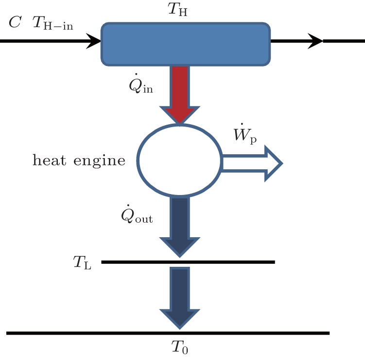 | Fig. 7. A special heat– work conversion system in which the working fluid is heated by a hot stream. |
For the system, we have[27]

where UH is the thermal conductance of the heat exchanger, and

where UL is the thermal conductance between the low temperature heat source and the environment. For the system, we also have

Assume that the thermal conductances satisfy

and U = 20 W/K. Then, with Eqs. (28)– (31), the variations of the entransy loss rate and the output power with UH can be shown in Fig. 8. It can be seen that the entransy loss rate and the output power reach their maximum values at the same time. The numerical results have verified the theoretical analyses.
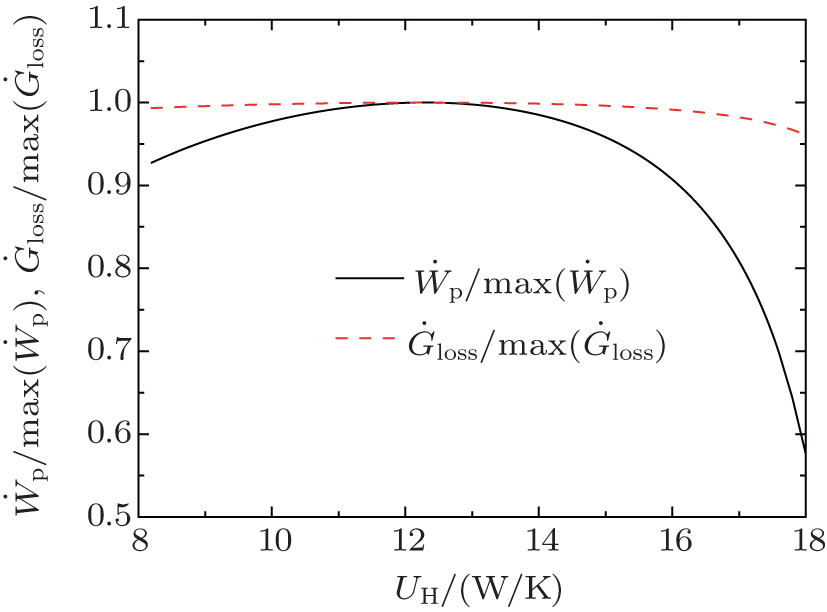 | Fig. 8. Variations of the entransy loss rate and output power with UH. |
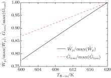
Furthermore, we can calculate the case in which the inlet temperature of the hot stream is not fixed. In this case, we assume that UH = UL = 10 W/K. Then, the variations of the entransy loss rate and the output power with TH– in can be obtained and shown in Fig. 9. It can be seen that larger entransy loss still leads to larger output power in this case. As the inlet temperature of the hot stream is not given, the heat flow rate from the hot stream is not given, either. The preconditions in Eq. (22) are not satisfied, but the concept of entransy loss is still applicable for this case.
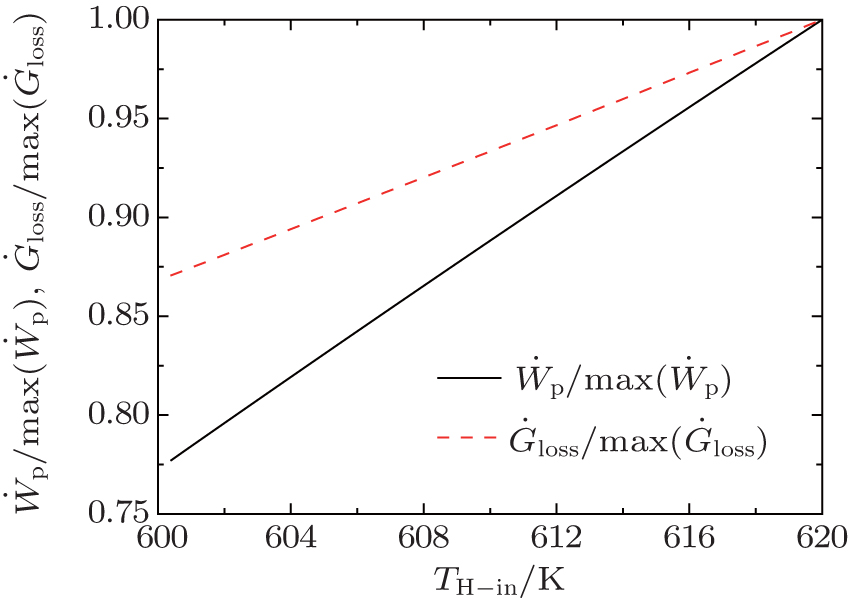 | Fig. 9. Variations of the entransy loss rate and output power with TH– in. |
Moreover, we can also discuss another special case of the system shown in Fig. 5. We assume that the temperatures of the high and low temperature heat sources are constants, TH and TL, respectively. Then, it is very clear that the heat leaks are independent of the heat flow into the working fluid of the thermodynamic cycle. Qleak– 1 and Qleak– 2 can change when neither Qin nor the heat engine change. In this kind of case, the heat flow from the high temperature heat source is not a fixed value any more. With Eq. (22), it can be seen that the entransy loss may change when the output work keeps constant. Therefore, when the preconditions are not satisfied, larger entransy loss may not lead to larger output work.
In this paper, the entransy theory is extended to the analyses of the heat– work conversion systems with inner irreversible thermodynamic cycles.
For different inner irreversible factors, their influences on entransy loss are discussed. The relationships between the entransy loss and the output work of the discussed thermodynamic cycles are obtained. It is found that the concept of entransy loss can also be used to analyze the inner irreversible thermodynamic cycles.
Furthermore, the common heat– work conversion systems with inner irreversible thermodynamic cycles are analyzed. As a specific example, the heat– work conversion system, in which the working fluid of the thermodynamic cycles is heated and cooled by streams, is analyzed. We find that larger entransy loss leads to larger output work when the total heat flow from the high temperature heat source and the corresponding equivalent temperature are fixed. This is verified with numerical results. On the other hand, it is also found that larger entransy loss does not always lead to larger output work when the preconditions are not satisfied.
| 1 |
|
| 2 |
|
| 3 |
|
| 4 |
|
| 5 |
|
| 6 |
|
| 7 |
|
| 8 |
|
| 9 |
|
| 10 |
|
| 11 |
|
| 12 |
|
| 13 |
|
| 14 |
|
| 15 |
|
| 16 |
|
| 17 |
|
| 18 |
|
| 19 |
|
| 20 |
|
| 21 |
|
| 22 |
|
| 23 |
|
| 24 |
|
| 25 |
|
| 26 |
|
| 27 |
|