
Direct evidence of high temperature superconductivity in one-unit-cell FeSe films on SrTiO3 substrate by transport and magnetization measurements*
[Xing Yinga), b) , Wang Jiana), b)  ]
]
]
|
|


†Corresponding author. E-mail: jianwangphysics@pku.edu.cn
*Project supported by the National Basic Research Program of China (Grant Nos. 2013CB934600 and 2012CB921300), the National Natural Science Foundation of China (Grant Nos. 11222434 and 11174007), and the Research Fund for the Doctoral Program of Higher Education (RFDP) of China.
Zero resistance and Meissner effect are two crucial experimental evidences of superconductivity in determining a new kind of superconductor, which can be detected by transport and diamagnetic measurements. In this paper, we briefly review the main transport and magnetization results on the one unit cell (1-UC) FeSe films grown on SrTiO3 (STO) substrates from our team in recent years, which identify the high temperature superconductivity in 1-UC FeSe films.
The discovery of superconductor La[O1− xFx]FeAs (x = 0.05– 0.12) with transition temperature (Tc) of 26 K in 2008[1] triggered an impressive amount of experimental and theoretical studies in condensed matter physics and material science.[2– 7] It is unexpected that superconductivity exists in compounds which contain the element Fe since normally ferromagnetism is against superconductivity. Therefore, this discovery causes worldwide effort to understand the nature of the superconductivity in iron-based superconductors. So far, four basic types have been discovered: LaFeAsO “ 1111” type, [8] MFe2As2 “ 122” type, [9] MFeAs “ 111” type, [10] and FeSe “ 11” type, [11] with the maximum Tc climbing as high as 55 K[5] and 56 K[12, 13] in the bulk materials. Similar to cuprates, the naturally layered iron based superconductor has been demonstrated as another high temperature superconductor.
When one dimension of a bulk superconductor decreases to smaller than the coherence length of the Cooper pairs, the superconductor can be considered as a quasi-two dimensional (quasi-2D) superconductor.[14] Due to thermo and quantum fluctuations, which are more severe in the low dimensional system, the superconductivity should be suppressed by decreasing the thickness of a superconducting film, which has been confirmed by many groups.[15– 17] However, for quasi-2D superconductors epitaxially grown on substrates, the interface may promote Tc by enhancing the electron– phonon coupling[18] and the epitaxial strain.[19] Recently, atomically flat one unit cell (1-UC) thick β -FeSe films have been successfully grown on STO (001) substrates by molecular beam epitaxy (MBE) technique.[20] For the 1-UC FeSe on STO, a superconducting-like energy gap as large as 20 meV obtained from in situ scanning tunneling spectra (STS)[20] or 15 meV (disappear at 65± 5 K) detected by in situ angle-resolved photoemission spectroscopy (ARPES)[21, 22] was observed, which is much larger than Δ ∼ 2.2 meV for bulk FeSe (Tc∼ 8 K at ambient pressure[11]). Then, the key question for these observations is if the observed gap in the 1-UC FeSe films is really the superconducting gap. Thus, the direct evidences of zero resistance and the Meissner effect are necessary to demonstrate the enhanced superconductivity in the 1-UC FeSe films.
For the ex situ transport and diamagnetic measurements, the 1-UC FeSe films must be taken out of the ultrahigh vacuum (UHV) system. Since the atmosphere condition can easily destroy the superconductivity in such thin films, only 5-UC FeSe films covered by amorphous Si protection layer (20 nm) were measured[20] before our work of ex situ transport measurements. Although the superconducting transition in resistance for 5-UC FeSe was observed, the zero resistance was not detected. Therefore, to surely determine the superconductivity of the 1-UC FeSe films by ex situ measurements is quite challenging but very important.
Here, the zero resistance and the Meissner effect evidences of high temperature superconductivity in 1-UC FeSe films with enhanced Tc, upper critial field Hc2, and critical current density Jc, detected by ex situ transport and magnetization measurements, which were firstly reported by our team, are reviewed.
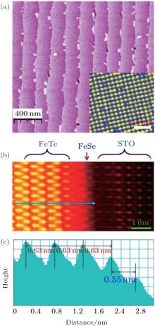
The 1-UC β -FeSe films (a Se– Fe– Se triple layer with thickness of 0.55 nm) were synthetized by an MBE system, starting from Fe and Se powders with a flux ratio of 1:10 on the STO(001) substrates.[23] The atomically flat 1-UC FeSe film (Fig. 1(a)), with in-plane lattice constants a = b = 3.82 Å , has a lattice mismatch of 2.36% with the STO substrate (3.91 Å ). The 1-UC FeSe is too thin to survive in the atmosphere. So searching for a suitable protecting layer is a significant step for ex situ studies. In our measurements, non-superconducting FeTe layers (10 UC) were chosen to cover the 1-UC FeSe film by MBE since FeTe can be epitaxially grown on the FeSe film and protect the FeSe film well. Figures 1(b) and 1(c) show scanning transmission electron microscope (STEM) images of two sharp interfaces from the cross-section of the FeTe/FeSe/STO heterostructure, which demonstrate the good quality of the 1-UC FeSe film after depositing the protection layer. For further protection, an amorphous Si film is used as the second cover layer grown on the FeTe film to avoid oxygen incorporation into the FeTe film and further protect the FeSe sample.
 | Fig. 1. (a) STM image of a typical 1-UC FeSe film. The steps originate from the STO substrate and the inset shows the atomic-resolution image. (b) The high-angle annular dark field STEM image of a (10-UC)FeTe/(1-UC)FeSe/STO heterostructure, showing two very sharp interfaces. (c) The line profile corresponding to the blue line in panel (b), confirming the distinct FeTe cover layer, the FeSe film, and the SrTiO3 substrate.[23] |
For transport measurements, standard four-electrode or six-electrode measurements were used for the Si/(10-UC)FeTe/(1-UC)FeSe/STO heterostructure with an area of ∼ 8 mm× 1.5 mm (see the inset of Fig. 2(a)). The temperature dependence of resistance under zero magnetic field exhibits an obvious onset superconducting drop with 


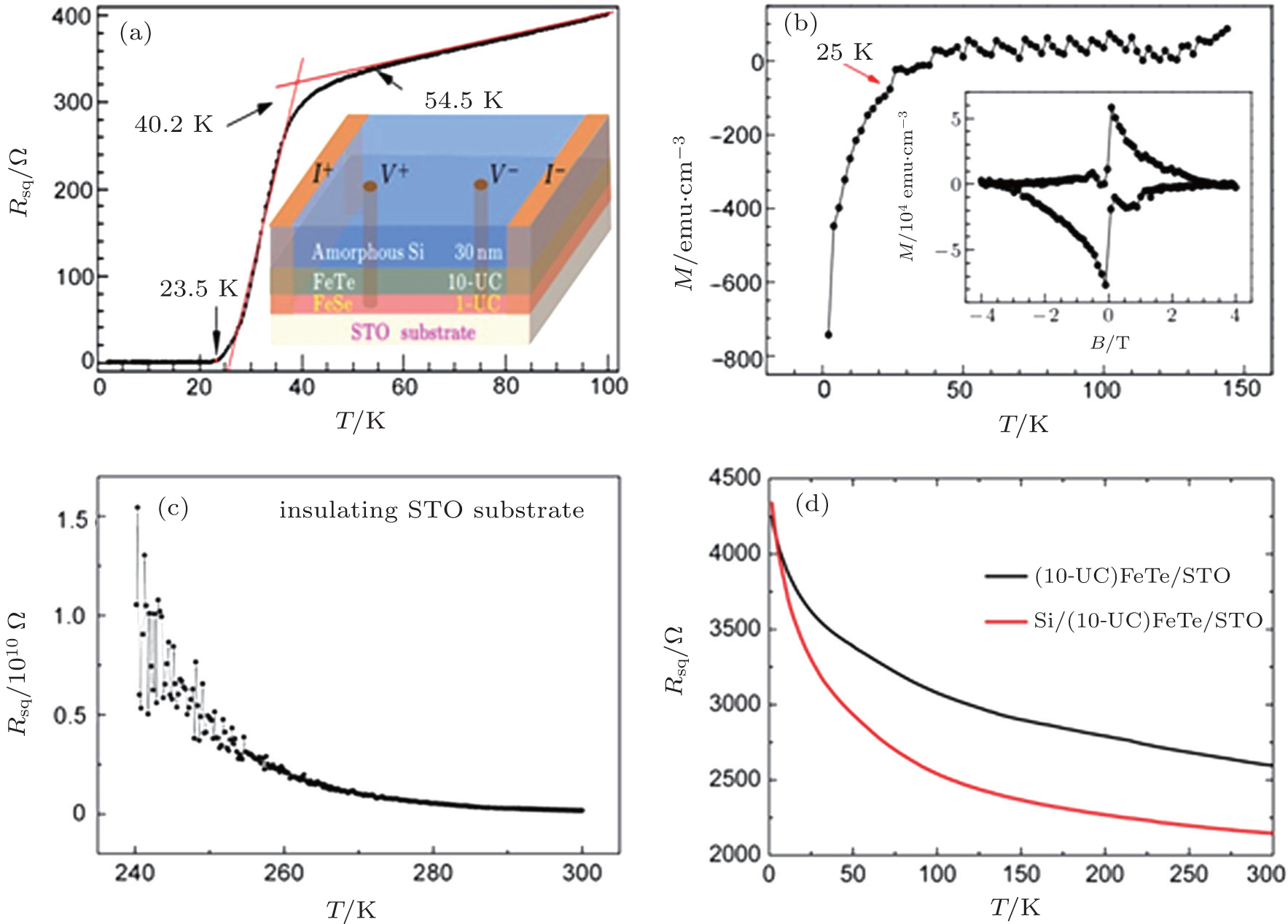 | Fig. 2. (a) The R(T) curve of superconducting Si/(10-UC)FeTe/(1-UC)FeSe/STO heterostructure, showing   |
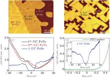
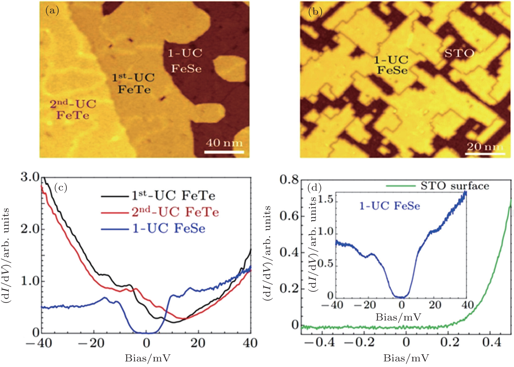 | Fig. 3. (a) STM image of 1-UC FeSe film partially covered by the (1-UC & 2-UC) FeTe protection layer on conductive STO substrate. (b) STM image of the 1-UC FeSe film with some parts of the STO surface exposed. (c) The typical dI/dV spectra taken on the 1st-UC FeTe, the 2nd-UC FeTe, and the 1-UC FeSe films. (d) The typical dI/dV spectra taken on 1-UC FeSe film and exposed STO surface.[23] |
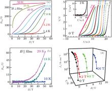
 | Fig. 4. Characterization of the superconductivity. Magnetoresistance measured in (a) perpendicular and (b) parallel magnetic fields with pulsed magnetic field up to 52 T. (c) The V(I) curves measured at temperatures ranging from 2 K to 50 K in zero magnetic field. (d) The Jc calculated from Ic at various temperatures and perpendicular magnetic fields.[23] |
We would like to mention that the indium electrodes we used can easily penetrate through the protection layers (here ∼ 50 nm thick) and connect the FeSe film by directly pressing the electrodes on the top surface of the Si/(10-UC)FeTe/(1-UC)FeSe/STO heterostructure. Thus, it is not surprising ex situ transport and diamagnetic measurements reveal the superconductivity in multi-UC FeSe films, [23, 27] although the STM data shows non-superconducting behavior for the top surface of the multi-UC FeSe film.[20] Based on the above discussion, we believe that only the first UC FeSe on STO superconducts even that the FeSe film is multi-UC thick.
To determine Hc2 of the 1-UC FeSe film, pulsed high magnetic fields up to 52 T were applied perpendicular and parallel to the film (Figs. 4(a) and 4(b)) for the measurements. Anisotropic and robust superconductivity is observed. In the perpendicular magnetic field, the sample remains in the zero resistance state until the field increases to 40 T at 1.4 K. Even 52 T can hardly tune the film to its normal state, unless the temperature is near Tc. As for the parallel field situation, at 10 K, the sample shows zero resistance up to 52 T, revealing a much higher critical magnetic field than that in the perpendicular situation. This observation is consistent with the anisotropic behavior of a typical 2 D superconductor. The Hc2(0) is estimated to be 37 T for bulk FeSe, and is increased from 37 T to 72 T by applying a pressure of 1.48 GPa.[28] Therefore, the estimated value (∼ 80 T) of perpendicular critical field Hc2 in the 1-UC FeSe/STO system is enhanced compared to that of bulk FeSe.
In addition, the thin FeSe superconducting film shows an unexpected large critical current. The zero field voltage versus current (V(I)) curves at various temperatures are exhibited in Fig. 4(c). At 2 K, the critical current is as large as 13.3 mA, as shown in the inset. The derived temperature and magnetic field dependences of Jc for the 1-UC FeSe film are shown in Fig. 4(d) by considering the thickness of 0.55 nm of the superconducting layer as we confirmed above. At 2 K, Jc is 1.7× 10⁶ A/cm2, which is one order of magnitude higher than that of FeTe0.61Se0.39 crystal[29] and two orders larger than that of bulk FeSe (Jc ∼ 104 A/cm2).[30]
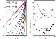
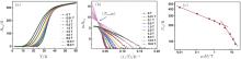
The signature of Berezinski– Kosterlitz– Thouless (BKT) like behavior is observed in the 1-UC FeSe film as another evidence of 2D superconductivity.[31, 32] As shown in Fig. 5(a), the V(I) curves of 1-UC FeSe just below Ic can be fitted by a power-law dependence (V ∝ Iα ). Figure 5(b) reveals that the exponent α approaches 3 at T = 23.1 K. This temperature is therefore identified as TBKT. Furthermore, the BTK-like fitting for R(T) characteristics (Fig. 5(c)) also indicates a TBKT of 23.0 K, which is consistent with the fitting result from the V(I) curves.
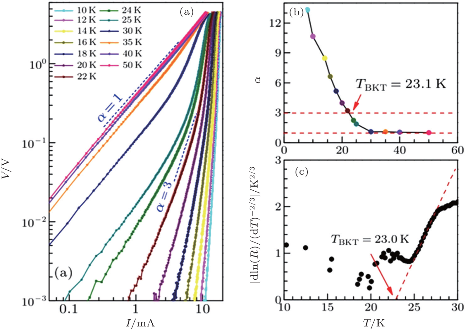 | Fig. 5. BKT like transition of 1-UC FeSe films. (a) The V(I) curves at different temperatures, the two dashed lines correspond to V∼ I and V ∼ I3. (b) The power-law exponent α (V∼ Iα ) as a function of temperature, with α = 3 (T ∼ 23.1 K) indicating BKT transition. (c) The R(T) curve plotted on a [d ln(R)/dT]− 2/3 scale. The dashed line is the behavior expected for a BKT transition with TBKT = 23.0 K.[23] |
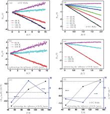
For a typical type-II superconductor, the dissipation behavior is influenced by the competition beteween the pinning forces (the pinning force dominated flux creep regime) and the Lorentz force (the Lorentz force dominated flux flow regime) in an external magnetic field. To evaluate the extent to which formalism is applicable for our 1-UC FeSe films, the resistance versus temperature curves of the 1-UC FeSe film in various magnetic fields were measured (Fig. 6(a)).[33] Figure 6(b) reveals the corresponding ln[Rsq] vs. 1/T relations. The thermally activated flux flow (TAFF) of the vortex region can be described by the Arrhenius relation: ρ (T, H) = ρ (H) exp[− U0(H)/T], where U0 is the activation energy in the absence of a gradient.[34] Linear fits are performed on the low-temperature part (large 1/T behavior), which are shown as solid pink lines. The slopes obtained from these fits yield the activation energies U0(H) in various magnetic fields (see Fig. 6(c)). The plots of ln[Rsq] vs. 1/T for various fields have a common intersection point, which should ideally correspond to the Tc of the superconducting specimen. In this sample, the intersection point corresponds to a temperature of Tm ∼ 38 K, which is close to the middle point Tc from the Rsq vs. T curves. Besides, power-law fits (H − γ ) are performed on the U0(H) data and the two regimes are clearly visible with a crossover occurring at a characteristic field μ 0H (≈ 3.4 T), with different exponents γ on the two sides (γ = 0.14 for μ 0H < 3.4 T and 0.60 for μ 0H > 3.4 T). A change in the exponent γ by about a factor of 4 across μ 0H with a relatively small value at low field suggests a crossover from a single-vortex pinning dominated regime to a collective flux creep regime across μ 0H. Similar crossover behaviors have been found in β -FeSe (μ 0H ≈ 3 T)[30] and SmFeAsO0.85 (μ 0H ≈ 3 T)[35] bulk crystals.
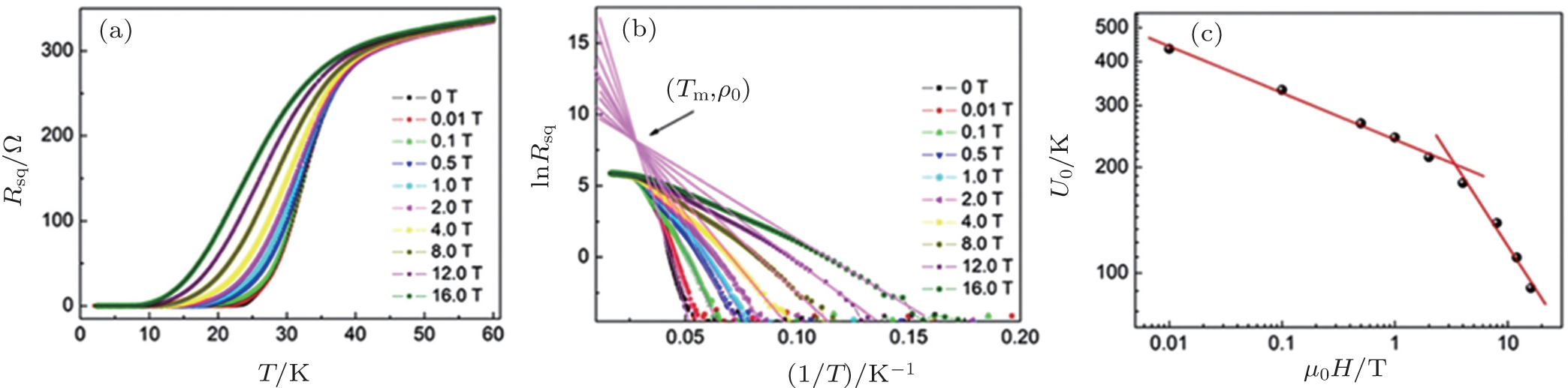 | Fig. 6. Arrhenius TAFF analysis. (a) Temperature dependence of resistance in different magnetic fileds. (b) ln[Rsq] vs. 1/T in various perpendicular magnetic fields. The corresponding solid lines are fitting results from the Arrhenius relation. (c) Field dependence of U0(H). The solid lines are power-law fits using U0(H) ∼ H− γ . For this 1-UC FeSe film, γ = 0.14 for μ 0H < 3.4 T, and γ = 0.60 for μ 0H > 3.4 T.[33] |
The nature of charge carriers in the normal state is one of the crucial ingredients which are required to understand the mechanism of superconductivity. We performed Hall effect measurements for the 1-UC FeSe films. The electronic contacts for the Hall measurements were made in 6-electrode geometry by using indium spheres and 25 μ m diameter gold wires. The Hall resistance (Rxy) was obtained by sweeping the magnetic field at a fixed temperature. The Rxy vs. magnetic field curves at different temperatures (Figs. 7(a) and 7(d)) exhibit a good linear relation. For the two FeSe films we studied, 
 | Fig. 7. Hall results of 1-UC FeSe films grown on intrinsic STO substrate. The Rxy(H) curves at different temperatures of 1-UC FeSe film without (a) and with (b) subtracting the background. (c) Hall coefficient and the carrier density calculated from data in panel (b). (d)– (f) Data from another 1-UC FeSe sample.[33] |
A similar Hall coefficient sign reversal behavior has also been found in bulk FeTe0.6Se0.4[36] and FeCr0.02Se, [37] which is usually interpreted by the multiband effect of the electronic structure and the coexistence of electron and hole carriers with different contributions from various bands. This Hall coefficient sign reversal behavior has also been investigated with different annealing time and the characteristic temperature (Te− h) increases with annealing time, [38] indicating a close relationship between superconductivity and the nature of the charge carriers.
Compared with in situ STM (estimated Tc ∼ 80 K)[20] and ARPES (estimated Tc ∼ 65 K)[21, 22] data on 1-UC FeSe films growing on conductive STO substrates, our ex situ measurements of the FeSe films on intrinsic STO substrates exhibit relatively lower transition temperature with 

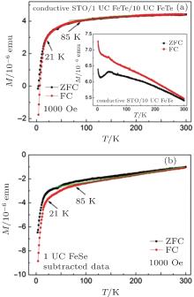
However, the ex situ diamagnetic property of FeSe films on conductive STO substrates measured by our group indicates a hint of Tc above the liquid nitrogen temperature.[33, 39] The magnetic characterization of a 1-UC FeSe film grown on conductive STO substrate under a parallel magnetic field of 1000 Oe is shown in Fig. 8(a). The data are shown for the zero-field cooled (ZFC) and field cooled (FC) modes. After subtracting the signal from the protection layer and the substrate, we find a diamagnetic drop below T∼ 85 K which may correspond to superconductivity (Fig. 8(b)). This is nearly ten times larger than the Tc of bulk FeSe and even higher than the record value of Tc∼ 56 K[12, 13] in bulk iron-based superconductors. However, the unusual phenomenon that the diamagnetic signal in FC mode is stronger than that in ZFC mode still remains unclear. We will leave this for further investigation.
 | Fig. 8. Diamagnetic measurements of 1-UC FeSe films grown on conductive STO substrate. (a) Data shown for ZFC and FC measurements in 1000 Oe parallel magnetic field. Inset: the M(T) curves of conductive STO/non-superconducting 1-UC FeSe/10-UC FeTe. (b) The M(T) curves of 1-UC FeSe (subtracting the influence of STO substrate and FeTe protection layer).[33] |
One recent work also reported the indication of superconductivity with Tc above liquid nitrogen temperature (even larger than 100 K) in FeSe/conductive STO system by means of in situ four-point probe (4PP) electrical transport measurement, which is much higher than the observed Tc by ex situ standard transport measurment in our work. One possible reason is that our 1-UC FeSe film is covered by a protective FeTe layer, which is known to be antiferromagnetic and may diminish Tc. Although there might be some pitfalls regarding the 4PP method, [39, 40] both in situ transport measurement and ex situ magnetization measurement show a hint that the FeSe/STO structure might become the second system with transition temperature higher than the boiling point of liquid nitrogen, while confirmatory experiments like in situ diamagnetic and standard four-electrode transport measurements are required to fully confirm this.
The understanding of extremely enhanced superconductivity in 1-UC FeSe films has attracted a tremendous amount of attention over the past few years. Why do Cooper pairs form at such high temperatures? What is the possible physical mechanism in this system? One recent high-resolution ARPES study[41] reveals shake-off bands in the 1-UC FeSe/STO system, suggesting the presence of bosonic modes. Such a mode may come from the interaction between oxygen optical phonons in STO and electrons in FeSe. It is suggested that this coupling is responsible for raising the opening temperature of the superconducting gap in 1-UC FeSe/STO.
The key experimental evidences of superconductivity in 1-UC FeSe films on STO substrates by ex situ transport and diamagnetic measurements are briefly reviewed. The interface enhanced superconductivity with high Tc, Hc, and Jc makes the FeSe ultra-thin films not only interesting for detecting and understanding high temperature superconductivity but also attractive for potential applications in superconducting electronics. We hope the studies in FeSe/STO heterostructures will open a door for exploring new unconventional superconductors by interface engineering.
We are grateful for all our collaborators for materials fabrication, helpful discussion, and experimental support.
| 1 |
|
| 2 |
|
| 3 |
|
| 4 |
|
| 5 |
|
| 6 |
|
| 7 |
|
| 8 |
|
| 9 |
|
| 10 |
|
| 11 |
|
| 12 |
|
| 13 |
|
| 14 |
|
| 15 |
|
| 16 |
|
| 17 |
|
| 18 |
|
| 19 |
|
| 20 |
|
| 21 |
|
| 22 |
|
| 23 |
|
| 24 |
|
| 25 |
|
| 26 |
|
| 27 |
|
| 28 |
|
| 29 |
|
| 30 |
|
| 31 |
|
| 32 |
|
| 33 |
|
| 34 |
|
| 35 |
|
| 36 |
|
| 37 |
|
| 38 |
|
| 39 |
|
| 40 |
|
| 41 |
|