
Effective method to control the levitation force and levitation height in a superconducting maglev system*
[Yang Peng-Tao, Yang Wan-Min , Wang Miao, Li Jia-Wei, Guo Yu-Xia]
, Wang Miao, Li Jia-Wei, Guo Yu-Xia]
|
|


†Corresponding author. E-mail: yangwm@snnu.edu.cn
*Project supported by the National Natural Science Foundation of China (Grant Nos. 51342001 and 50872079), the Key-grant Project of Chinese Ministry of Education (Grant No. 311033), the Research Fund for the Doctoral Program of Higher Education of China (Grant No. 20120202110003), the Innovation Team in Shaanxi Province, China (Grant No. 2014KTC-18), and the Fundamental Research Funds for the Central Universities, China (Grant Nos. GK201101001 and GK201305014), and the Outstanding Doctoral Thesis Foundation Project of Shaanxi Normal University, China (Grant Nos. X2011YB08 and X2012YB05).
The influence of the width of the middle magnet in the permanent magnet guideways (PMGs) on the levitation force and the levitation height of single-domain yttrium barium copper oxide (YBCO) bulks has been investigated at 77 K under the zero field cooled (ZFC) state. It is found that the largest levitation force can be obtained in the system with the width of the middle magnet of the PMG equal to the size of the YBCO bulk when the gap between the YBCO bulk and PMG is small. Both larger levitation force and higher levitation height can be obtained in the system with the width of the middle magnet of the PMG larger than the size of the YBCO bulk. The stiffness of the levitation force between the PMG and the YBCO bulk is higher in the system with a smaller width of the middle magnet in the PMG. These results provide an effective way to control the levitation force and the levitation height for the superconducting maglev design and applications.
One of the most important properties of superconductors is their ability to provide passive and stable levitation in the magnetic field produced by the permanent magnets, [1] which can be used in applications such as superconducting magnetic bearings, flywheels, generators, motors, trapped flux magnets, and transportation systems.[2– 6] The main advantage of the superconducting magnetic transportation system, compared to other levitation systems such as the electromagnetic levitation system, is its large levitation force, high stability, and no need for any feedback control system due to the unique properties of the REBCO bulks.[7– 9]
It is easy to make the magnetic levitation systems (composed of permanent magnets and REBCO bulks) have high stability and no feedback control system, the key problem is how to control the levitation force and the levitation height. The levitation force between a superconductor and a magnet can be calculated by the following formula:[10]
 |
The equation can be simplified in one dimension as
 |
with

where m is the magnetic moment of the superconductor, dH/dx is the magnetic field gradient produced by the external field, M is the magnetization per unit, v is the volume of the superconductor, A is a constant depending on the sample geometry, Jc is the critical current density of the superconductor, and r is the radius of the shielding current loop. This indicates that it is necessary to have r, Jc, and dH/dx as large as possible to acquire a high levitation force.
Large r can be achieved by using well-textured single-domain REBCO bulks, and high Jc has been achieved by introducing strong flux pinning centers in the samples.[11– 16] But for a given REBCO bulk superconductor, how do we achieve a large levitation force and a high levitation height? This is a key problem that needs solving for the levitation systems, especially for the superconducting maglev systems. It is very important to make clear what kind of permanent magnet configuration is suitable to obtain a large levitation force and a high levitation height.
Most guideways of the REBCO bulk superconducting maglev vehicles consist of three rows of magnets with antiparallel vertical magnetization, so the magnetic field distributions of the guideways are uniform along the longitudinal direction and have high magnetic field gradients in the lateral and vertical directions, which assure that the maglev vehicles can be levitated over the guideways and move smoothly along the guideways without any deviation from the maglev track. These kinds of guideways have been designed and used in China, [17, 18] Brazil, [19] and Spain.[20, 21] For example, a superconducting magnetic levitation system consisting of YBCO bulks with 30 mm in diameter and middle magnets with 12 mm in width is used in Southwest Jiaotong University, China.[22] A superconducting maglev consisting of YBCO bulks with 64 mm in width and middle magnets with 25 mm in width in a long PMG was designed by Federal University of Rio de Janeiro, Brazil.[23] There the size of the middle magnet and the REBCO bulk is not the same; which one is better? Yang et al. measured the levitation forces between a single-domain YBCO bulk and several magnets with different diameters at 77 K under the ZFC state, the results indicated that the largest levitation force can be obtained when the size of the magnet is the same as that of the YBCO bulk.[24] Is there any relationship between the width of the middle magnet and the size of the REBCO bulk for achieving higher levitation force or levitation height?
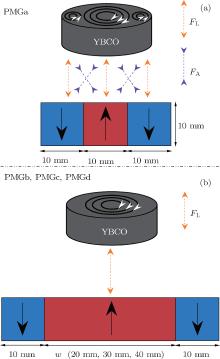
It is very important for a magnetic levitation transport system to have higher levitation force, higher levitation height, and higher stiffness, then it can have larger carrying capacity and higher stability. To identify the optimal middle magnet widths of the permanent magnet guideways (PMGs) for achieving the largest levitation force and the highest levitation height, PMGs with middle magnets of different widths and a single-domain YBCO bulk are studied. The configurations of the YBCO bulk and the PMGs are shown in Fig. 1.
 | Fig. 1. Configurations of the YBCO bulk and four PMGs (lateral cross section) for levitation force measurement. |
A cylindrical single-domain YBCO bulk with diameter (ds) 20 mm and height 7 mm, and four infinitely long PMGs along the y direction with lateral cross section of dimensions (20 mm+ w) × 10 mm (w = 10 mm, 20 mm, 30 mm, 40 mm) were used in this experiment. The single-domain YBCO bulk was fabricated by our lab, [25] the detailed process was described in Ref. [25]. The guideways consisted of 3 rows of magnets with antiparallel vertical magnetization, the side rows were paved with Nd– Fe– B magnets of dimensions 10 mm× 10 mm× 10 mm, and the middle one was paved with Nd– Fe– B magnets of dimensions 10 mm × w × 10 mm, as shown in Fig. 1. The levitation forces were measured using a home-made device, [26] the device involved a cantilever beam with a permanent magnet attached at the end, and the sample was immersed in liquid nitrogen in a container well below the guideways, which were driven towards or away from the superconductor with a screw that was driven by a controlling motor. The distance was measured by a displacement sensor and the levitation force was measured by a load cell. The distance and force data signals were continuously recorded by an x– y recorder. The magnetic field density could be measured with a Hall probe instead of the load cell. The fluctuation rate was less than 2.0% according to the measuring data before. In this paper, the levitation forces were measured at 77 K in the zero field cooled (ZFC) state.
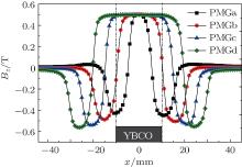
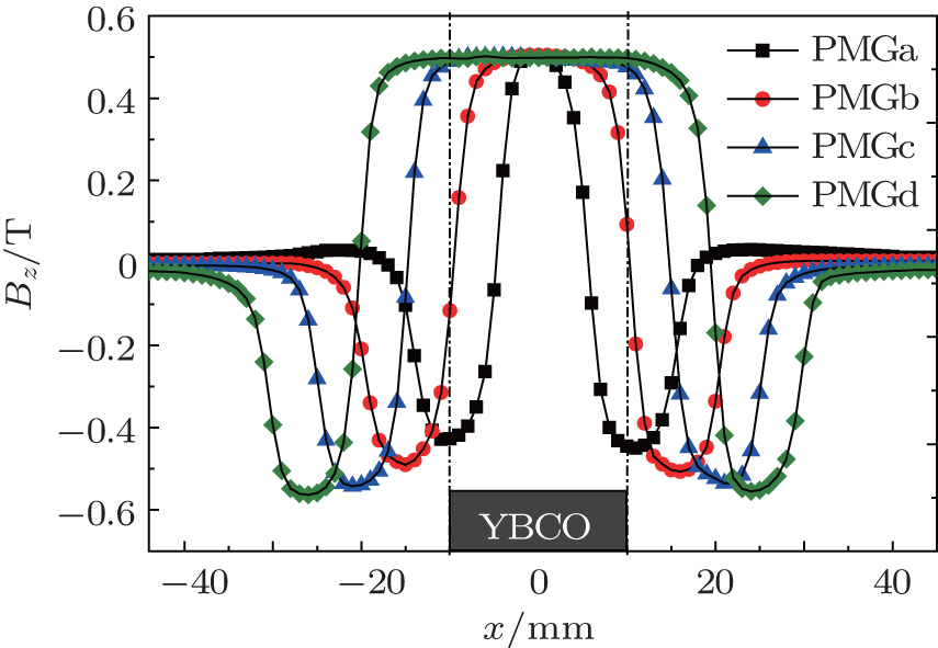 | Fig. 2. Magnetic field distributions along the x direction at the top surfaces of the PMGs. |
The vertical magnetic flux densities (Bz) on the top surfaces of the PMGs were measured along the x direction and shown in Fig. 2. As we can see from Fig. 2, the maximum Bz is nearly the same (0.5 T) for all the PMGs with different middle magnets, and the fluctuation rate is in the range of ± 0.01 T. But the magnetic field distributions of the PMGs are very different. The width of the homogenous magnetic field produced by PMGa (4 mm) is much smaller than ds (20 mm) of the YBCO bulk, and the higher magnetic field gradient at the edge of the middle magnet and the different magnetic polarities (positive in the middle and negative immediately adjacent to it) will result in three induced magnetic shielding current loops inside the YBCO bulk. The widths of the homogenous magnetic fields produced by PMGc (22 mm) and PMGd (32 mm) are larger than ds (20 mm), the homogenous magnetic field will result in only one induced magnetic shielding current loop inside the YBCO bulk, and the magnetic flux change rate (dΦ /dt) will be much smaller or even none when the YBCO bulk is very close to PMGc and PMGd. The width of the homogenous magnetic field produced by PMGb (16 mm) is a little less than ds (20 mm) and with only one magnetic polarity, this will lead to only one induced magnetic shielding current loop inside the YBCO bulk, and the magnetic flux change rate (dΦ /dt) will increase even when the YBCO bulk is very close to PMGb.
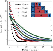
Figure 3 shows the levitation forces between the four PMGs and the YBCO bulk in the ZFC state measured at liquid nitrogen temperature. As we can see from Fig. 3, the maximum levitation forces and the shapes of the F– z curves of the samples are very different for the four PMGs, the maximum levitation force Fmax increases first and then decreases with the increasing widths of the middle magnets in the guideways, and the absolute gradient of the F– z curve decreases with the increasing widths of the middle magnets. It is also seen that the maximum attractive force decreases with the increasing widths of the middle magnets when the PMGs are away from the YBCO bulk, and the attractive force between the YBCO bulk and PMGa is much larger than the others, because there are three magnetic poles in the region covered by the YBCO bulk when PMGa is approaching to the bulk; while there is only one magnetic pole in the others. The phenomenon is mainly due to the magnetic force between the multiple magnetic poles and the multiple induced magnetic shielding current loops inside the YBCO bulk, as shown in Fig. 4(a). The interaction between the magnet with N pole (or S pole) and the magnetic shielding current loops inside the YBCO bulk induced by the magnet with S pole (or N pole) results in an additional attractive force between the YBCO bulk and the PMGs.
 | Fig. 3. The levitation forces vs. the distance between the YBCO bulk and PMGs at 77 K in the ZFC state. |
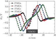
In order to make clear the influence of the middle magnet width of the PMGs on the levitation force of single-domain YBCO bulks, the maximum levitation forces of the samples were collected and plotted against the widths of the middle magnets, as shown in Fig. 5. The maximum levitation force increases first and then decreases with the increasing widths of the middle magnets, and the maximum levitation force (38.32 N) is obtained when the width of the middle magnet is 20 mm, which is equal to ds (20 mm) of the YBCO bulk. This is closely related to the magnetic field distribution of the PMGs. According to formula (2), the levitation force is determined by m and dH/dx, which means that large levitation force can be obtained with large m and dH/dx. The m of the YBCO bulk is determined by the induced electric current (I) and the radius (r) of the induced magnetic shielding current loops that are produced by the flux change rate (dΦ /dt) during the process of the YBCO bulk approaching the PMGs; dΦ /dt is determined by dΦ /dz because d Φ /dt = (dΦ /dz)× (dz/dt) = (dΦ /dz)× v and the moving speed of the PMGs to the YBCO bulk is of the same v; so the larger the d Φ /dz, the larger the m. The dH/dx can be determined by the magnetic flux density (Bx) distribution along the x direction, as shown in Figs. 6 and 7.
 | Fig. 4. The interaction between the induced magnetic shielding current loops in the YBCO bulk and the PMGs when they are approaching each other. Here FL and FA correspond to levitation and attraction, respectively. |
Because the maximum levitation forces are obtained when the gap between the YBCO bulk and the PMGs is about 0.5 mm, the result shown in Fig. 5 can be well interpreted by Eq. (2) based on Figs. 2 and 6. The number and the radius (r) of the induced magnetic shielding current loops produced in the YBCO bulk are closely related with the widths of the middle magnets in the PMGs, which can be divided into two types, one has three induced magnetic shielding current loops in the YBCO bulk, and the other has only one induced magnetic shielding current loop in the YBCO bulk, as shown in Fig. 4. We can see from Figs. 2 and 4 that the widths of the middle magnets in PMGb, PMGc, and PMGd wb, wc, wd ≥ ds, the middle magnets can cover the whole surface area of the YBCO bulk, and only one induced magnetic shielding current loop is produced in the bulk when they are moving closely together, this means that m is nearly the same for all the PMGs with w/ds ≥ 1; while dH/dx decreases with the increase of w, as shown in Figs. 6 and 7; which finally results in the decrease of the levitation force of the sample with the increase of w/ds from 1 according to Eq. (2). There are three induced magnetic shielding current loops in the YBCO bulk because the width of the middle magnet in PMGa (wa = 10 mm) is narrower than the diameter of the YBCO bulk (ds = 20 mm); as we can see from Fig. 4(a). The three magnetic poles of PMGa directly face and induce three magnetic shielding current loops inside the YBCO bulk so the radii of all the induced magnetic shielding current loops are less than that produced by PMGb, which results in a great reduction of m. In addition, there are still some attractive interaction forces between the magnets with N poles (or S poles) and the induced magnetic shielding current loops inside the YBCO bulk induced by the magnets with S poles (or N poles), which results in a reduction of the levitation force between the YBCO bulk and PMGa, even though the absolute value of dH/dx is a little larger than that of PMGb. When the width of the middle magnet is equal to the diameter of the YBCO bulk, such as for PMGb (wb = ds = 20 mm), there is only one induced magnetic shielding current loop inside the YBCO bulk, which corresponds to a relatively high value of m; and at the same time, dH/dx also has a high value (as shown in Figs. 6 and 7), then the largest levitation force is obtained between the YBCO bulk and PMGb.
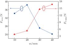
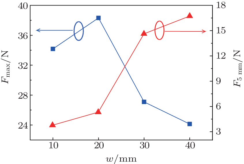 | Fig. 5. The levitation forces at the levitation heights of 0.5 mm (the maximum levitation force Fmax) and 5.0 mm (F5 mm) vs. the width (w) of the middle magnet of the PMGs. |
 | Fig. 6. The magnetic flux density (Bx) distributions of the PMGs along the x direction. |
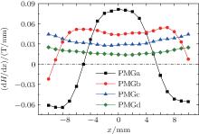
 | Fig. 7. The magnetic field gradient (dH/dx) of the four kinds of PMGs along the x direction within the x range from − 10 mm to 10 mm. |
It is worth noting that the largest levitation force in the system with the width of the middle magnet equal to the diameter of the YBCO bulk is obtained only when the gap between the YBCO bulk and PMGb is small; while for practical maglev applications, we need a large levitation force at a relatively high levitation height, so both the levitation force and the levitation height are the key technical parameters to be considered according to the details of the application. For instance, as we can see from Fig. 3, the largest levitation force of the YBCO bulk can be achieved by using the PMGb guideway only when the levitation height is low (z ≤ 3.3 mm), while the largest levitation force of the YBCO bulk can be achieved by using PMGd when the levitation height is higher (z > 3.3 mm). The maximum levitation forces of the YBCO bulk at the levitation height of 5.0 mm (F5 mm) are selected and plotted in Fig. 5. It is easy to see that levitation force F5 mm of the YBCO bulk increases with the increase of the width w of the middle magnets monotonically, F5 mm increases from 3.78 N to 5.32 N, 14.62 N, and 16.73 N when the width w of the PMGs increases from 10 mm to 20 mm, 30 mm, and 40 mm, respectively. This is because the vertical magnetic flux density (Bz) of the PMGs decreases faster with the decrease of the width of the middle magnet, this means that the wider the width of the middle magnet, the higher the vertical magnetic flux density Bz at the same gap between the YBCO bulk and the PMGs in the z direction. This indicates that the larger the width of the middle magnet of the PMG, the larger the levitation force of the YBCO bulk at higher levitation height. On the other hand, it is easy to see from Fig. 3 that the levitation force vs. distance curve is becoming steeper with the decrease of the widths of the middle magnets in the PMGs, which indicates that the stiffness is increasing with the decreasing widths of the middle magnets in the PMGs.
Through the actual measurement, we have demonstrated that the width of the middle magnet of the PMG with the same size (20 mm) as the YBCO bulk is an adequate choice for achieving the largest levitation force (Fmax = 38.32 N) when the gap between the YBCO bulk and the PMG is small (z ≤ 3.3 mm); larger levitation force and higher levitation height can be obtained at the same time with the width of the middle magnet of the PMG larger than the size of the YBCO bulk; the stiffness of the levitation force between the PMG and the YBCO bulk is higher in the system with a smaller width of the middle magnet in the PMG. It is difficult to obtain the largest levitation force, the highest levitation height, and the greatest stiffness simultaneously under a given condition, we can choose different PMGs according to whether we need higher levitation force, higher levitation height, or higher stiffness. These results provide a useful guide to control the levitation force and the levitation height by changing the widths of the middle magnets in the PMGs during designing a superconducting maglev.
The author would like to thank Dr. Yun Hua-Shi for her kind discussion about this work.
| 1 |
|
| 2 |
|
| 3 |
|
| 4 |
|
| 5 |
|
| 6 |
|
| 7 |
|
| 8 |
|
| 9 |
|
| 10 |
|
| 11 |
|
| 12 |
|
| 13 |
|
| 14 |
|
| 15 |
|
| 16 |
|
| 17 |
|
| 18 |
|
| 19 |
|
| 20 |
|
| 21 |
|
| 22 |
|
| 23 |
|
| 24 |
|
| 25 |
|
| 26 |
|