

Dual-band LTCC antenna based on 0.95Zn2SiO4-0.05CaTiO3 ceramics for GPS/UMTS applications
[Dou Gang† , Li Yu-Xia, Guo Mei]
, Li Yu-Xia, Guo Mei]
|
|


†Corresponding author. E-mail: skd_yizu@163.com
*Project supported by the Specialized Research Fund for the Doctoral Program of Higher Education of China (Grant No. 20133718120009), the Natural Science Foundation of Shandong Provence, China (Grant Nos. ZR2013FQ002 and ZR2014FQ006), the China Postdoctoral Science Foundation (Grant No. 2014M551935), the Qingdao Municipality Postdoctoral Science Foundation, China, and the Scientific Research Foundation of Shandong University of Science and Technology for Recruited Talents, China (Grant Nos. 2013RCJJ042 and 2014RCJJ052).
In this paper, we present a compact low-temperature co-fired ceramic (LTCC) dual-band antenna by using the electromagnetic coupling effect concept for global positioning system (GPS) and universal mobile telecommunication system (UMTS) applications. The overall dimension of the antenna is 8.6 mm × 13.0 mm × 1.1 mm. It consists of double meander lines and a via hole line. The top meander line operates at the upper band, and the bottom radiating patch is designed for the lower band. The via-hole line is employed to connect the double meander lines. Because of the effect of the coupled line, total dimension of the proposed antenna is greatly reduced. With the 2.5: voltage standing wave ratio (VSWR) impedance bandwidth definition, the lower and upper bands have the bandwidths of 110 MHz and 150 MHz, respectively. The proposed antenna is successfully designed, simulated, and analyzed by a high frequency structure simulator (HFSS). And the antenna is manufactured by using the 0.95Zn2SiO4-0.05CaTiO3 ceramics ( εr = 7.1, tan δ = 0.00038) that is prepared by ourselves. The results show that the antenna is compact, efficient, and of near omnidirectional radiation pattern.
Owing to the rapid growth of the modern wireless communication, such as global positioning system (GPS) and universal mobile telecommunication system (UMTS), the demand for antennas which are capable of operating at multiband with compact size is increasing. However, it is not an easy task to design these antennas. In order to overcome the limit of conventional planar antenna structure, the utilization of multilayer low temperature co-fired ceramic (LTCC) technology gives the possibility of building highly integrated circuits in a single substrate.[1, 2] It enables a significant number of circuit components to be integrated within a module by embedding them in a multilayer substrate. Therefore, LTCC technology is able to produce compact and multiband antennas.
In previous researches, various kinds of antennas have been reported to meet the need for multiband and wideband operations.[3– 7] The microstrip line antennas, which can be employed to provide wide impedance bandwidth, low profile and easy manufacture, [8, 9] have many advantages, but they have a disadvantage of being large in size. A compact triple-band antenna has been proposed for the mobile band (RFID, PCS, WiBro) by using coupled meander line structure and stacking technique with the LTCC processing method.[10] In addition, a novel LTCC antenna with two open asymmetrical rectangular loops has been proposed, which can be used as ultra wideband (UWB) antenna and multiband communications.[11] However, this open asymmetrical rectangular loop structure deteriorates the radiation patterns, especially at higher frequencies.
In this paper, we propose a compact LTCC antenna which shows double wide operating bands to cover the GPS/UMTS bands. The antenna is composed of two meander radiating elements and a via-hole line embedded in an LTCC-body substrate. The coupling structure is used in the antenna with little additional volume. Meanwhile, the antenna is manufactured by using the 0.95Zn2SiO4-0.05CaTiO3 ceramics (ε r = 7.1, tanδ = 0.00038) which was prepared previously.[12] The design, return loss, impedance bandwidth, and radiation pattern characteristics of the proposed antenna are discussed.
Zn2SiO4 and CaTiO3 compounds were individually synthesized by a conventional solid-state reaction method through using reagent-grade powders: ZnO (99.6%), SiO2 (99.7%), CaCO3 (99.5%), and TiO2 (99.6%). For preparing the Zn2SiO4 and CaTiO3 compounds, the high-purity raw materials were weighed according to the desired stoichiometry, ball-milled in a polyethylene jar containing zirconia balls with ethanol for 4 h. After drying at 80 ° C, the mixed powders were individually ground and then calcined at 1250 ° C for 3 h and 1100 ° C for 2 h in air. The compounds were re-milled for 4 h according to the desired composition: 0.95Zn2SiO4-0.05CaTiO3 doped with 4.0 wt% Li2CO3-H3BO3. Then the mixed powders were dried, granulated, ball-milled with dispersant, defoamer, solvent and binder for 24 h in a nylon pot and cast into green sheets of 55-μ m thickness by the doctor-blade method.
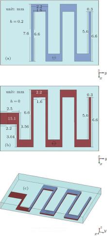
The geometry of the dual-band LTCC meander antenna is shown in Fig. 1. The LTCC antenna occupies a volume of 8.6 mm × 13.0 mm × 1.1 mm, and is composed of double layer (top layer and bottom layer) and a via-hole line. The currents along the x-axis are opposite in the meander antenna, hence they contribute little radiation in the desired direction. On the other hand, the radiating fields along the y axis in the meander radiating structure have the same direction, they have the characteristics of short dipole. Consequently, the meander line structure is adopted to increase its electrical surface-current length. The top meander line generates the first resonant mode of the proposed antenna. Here, the coupled lines that have different ratios of horizontal/vertical parts are used to adjust the effective surface-current path by inductive loading, which reduces the required size of the proposed antenna for a fixed operating frequency. The bottom meander line is designed for the second operation band. And the via-hole line is employed to connect them into a double meander line.
 | Fig. 1. Geometry and dimensions of the dual-band LTCC antenna using meander line structure: (a) Top view of top meander patches, (b) top view of bottom meander patches, (c) prospective view of the antenna. All dimensions are in unit mm. |
The permittivity and linear shrinkage of the 0.95Zn2SiO4-0.05CaTiO3 ceramic for the antenna implementation is 7.1 and 7.5% (sintered at 950 ° C).[12] The 0.95Zn2SiO4-0.05CaTiO3 green sheets were laminated at 50 ° C to form a ceramic block, which was applied to Ag meander lines, and then cut it into rectangular blocks (9.3 mm × 14.1 mm × 1.2 mm). Subsequently, the binder was removed by heating at 330 ° C in air for 1 h. And then the rectangular blocks were sintered at 950 ° C for 2 h, with the heating and cooling rates being 3.33 ° C/min. The antenna was mounted on FR-4 substrate with a relative permittivity of 4.4 and thickness of 1.6 mm. A 50-Ω coplanar waveguide (CPW) was used to feed the compact dual-band antenna. Crystalline phases of the antenna were identified by the x-ray diffraction (XRD: PANalytical B.V., X’ Pert PRO) using Cu Kα radiation. The microstructures were characterized by scanning electron microscope (SEM: Philip, XL30TM). The return loss of the proposed antenna was measured by an Agilent network analyzer (E5071C).
The XRD pattern of the antenna based on 0.95Zn2SiO4-0.05CaTiO3 is shown in Fig. 2(a). It shows that the antenna contains the two phases of Zn2SiO4 (JCPDS # 72-1856) and CaTiO3 (JCPDS # 82-0231). The SEM micrograph of the antenna is shown in Fig. 2(b). The ceramic is dense with grain sizes of 3 μ m– 5 μ m after being sintered at 950 ° C for 2 h in air.
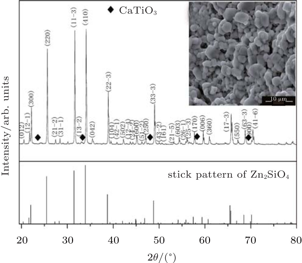 | Fig. 2. The XRD pattern of the antenna based on 0.95Zn2SiO4-0.05CaTiO3 after sintered at 950 ° C for 2 h in air. The inset shows the SEM micrograph of the antenna. |
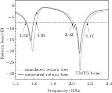
The top meander patch resonates at 2.1 GHz and the bottom radiating patch resonates at 1.58 GHz. Figure 3 shows the simulated and measured return loss of the antenna. With the 2.5:1 VSWR impedance bandwidth definition, the upper band of the simulated antenna has a bandwidth of 150 MHz (2.02 GHz– 2.17 GHz), which is wide enough to cover the UMTS bands. The lower band of the simulated antenna has a bandwidth of 110 MHz (1.52 GHz– 1.63 GHz), which satisfies the operating bandwidth of the GPS band. It can be seen that the measured return loss of the antenna is mainly in agreement with the simulated return loss, with the exception that the frequency shifts to the left slightly. The surface electrode of LTCC antenna is connected with CPW FR-4 substrate, which ensures the current feed. Meanwhile, it also increases the length of the surface-current path, thus reducing the frequency.
 | Fig. 3. Simulated and measured return loss of the dual-band LTCC antenna. |
Besides the return loss, the radiation patterns of the proposed dual-band antenna are examined as well. The simulated radiation patterns of the antenna in the H-plane and E-plane at 2.1 GHz and 1.58 GHz are depicted in Figs. 4(a) and 4(b), respectively. It is observed that the radiation patterns have nearly omnidirectional characteristic in the H-plane and quasi dumb-bell shape in the E-plane. In other words, the antenna behaves like a Y-directed electric dipole.
 | Fig. 4. Simulated radiation pattern of the dual-band LTCC antenna at (a) 2.1 GHz and (b) 1.58 GHz. |
A CPW-fed compact dual-band antenna is proposed for GPS/UMTS applications by using the meander line structure, coupled line theory, and stacking technique based on LTCC technology. Then, the antenna is manufactured by using 0.95Zn2SiO4-0.05CaTiO3 ceramics (ε r = 7.1, tanδ = 0.00038) which are prepared by ourselves. The antenna produces two work bands at 1.52 GHz– 1.63 GHz and 2.02 GHz– 2.17 GHz, and its dimensions are 8.6 mm × 13.0 mm × 1.1 mm. With the 2.5:1 VSWR impedance bandwidth definition, the lower and upper bands have impedance bandwidths of 110 MHz and 150 MHz, respectively. The antenna has approximately omnidirectional pattern with the stable gain, though it has simple structure and very compact size. Thus, the dual-band antenna is suitable for GPS/UMTS applications.
| 1 |
|
| 2 |
|
| 3 | [Cited within:1] |
| 4 |
|
| 5 |
|
| 6 |
|
| 7 |
|
| 8 |
|
| 9 |
|
| 10 |
|
| 11 |
|
| 12 |
|