


Single-layer dual-band terahertz filter with weak coupling between two neighboring cross slots
[Qi Li-Meia), b) , Li Chao†a)  , Fang Guang-You
a) , Li Shi-Chaoa) ]
, Fang Guang-You|
|


†Corresponding author. E-mail: cli@mail.ie.ac.cn
*Project supported by the National Natural Science Foundation of China (Grant Nos. 11174280 and 61107030), the Knowledge Innovation Program of the Chinese Academy of Sciences (Grant No. YYYJ-1123), and the China Postdoctoral Science Foundation (Grant No. 2012M520377).
A dual-band terahertz (THz) filter consisting of two different cross slots is designed and fabricated in a single molybdenum layer. Experimental verification by THz time-domain spectroscopy indicates good agreement with the simulation results. Owing to the weak coupling between the two neighboring cross slots in the unit cell, good selectivity performance can be easily achieved, both in the lower and higher bands, by tuning the dimensions of the two crosses. The physical mechanisms of the dual-band resonant are clarified by using three differently configured filters and electric field distribution diagrams. Owing to the rotational symmetry of the cross-shaped filter, the radiation at normal incidence is insensitive to polarization. Compared with the THz dual-band filters that were reported earlier, these filters also have the advantages of easy fabrication and low cost, which would find applications in dual-band sensors, THz communication systems, and emerging THz technologies.
Recently, considerable attention has been paid to realizing terahertz (THz) devices due to their wide range of applications, including chemical and biological sensing, imaging, security, and communications.[1– 3] A band pass filter is an important device in communication since it can block unnecessary signals from our interested band and increase the ratio of signals to noise within the interested band. In the THz band, most researchers have focused on the design and fabrication of band pass filters within a single pass band.[4– 8] However, multiple-band band pass filters are needed for astronomical applications.[9, 10] In addition, a recent trend in THz communication systems is to use multiple frequency bands and multiple beams to significantly increase the communication capacity.[11, 12] This provides an economical means to develop multi-mission systems and create potential demand for multi-band THz filters.
In the THz band, dual-band[13– 15] and triple-band[16] absorbers have been demonstrated widely, The special feature of these absorbers is that their units possess two or three kinds of resonators to create a dual-mode or triple-mode resonance responses. Like the multi-band absorbers, multiple-band bandpass filters can be obtained by introducing two or more different resonances in one unit cell. A metal-dielectric dual-band filter consisting of double four-legged loaded slots with different dimensions in one unit cell has been investigated theoretically, and it was found that the resonant frequencies occurred at 0.183 THz and 0.22 THz[17] while no further experimental demonstration was carried out for the structure. By depositing identical metallic frequency selective surface layers on the upper and lower sides of a quartz crystal to form a metal-dielectric-metal sandwiched structure, second-order bandpass THz filters were fabricated; [18– 20] however, the bandwidth of the second band was limited and the dielectric substrate became very fragile when its thickness decreased to less than 150 μ m. On the other hand, since these metal-dielectric-metal filters were fabricated on dielectric substrates, it would be easy to bring a large insertion loss. In addition, the fabrication processes are relatively complicated compared with those for a metal-dielectric or single-layer metal structure.
In the present paper, a THz single-layer dual-band filter consisting of two neighboring cross slots with different dimensions is designed and fabricated. Experimental results measured by a THz time-domain spectroscopy system show excellent agreement with the simulation results. Unlike the most commonly used metal– dielectric structure[17] or metal– dielectric– metal sandwiched structures, [18– 20] the dual-band filters are designed with only one metal layer, which makes its fabrication easy and keeps the cost low. In addition, the design process is straightforward and simple according to the physical concept and some formulas. Owing to the weak coupling between the two neighboring cross slots in the unit cell, good selectivity performance can be easily achieved, both in the lower and higher bands, by the tuning dimensions of the two crosses. The physical mechanisms of the dual-band resonant responses are also clarified.
Figure 1(a) shows the top view of the 2 × 2 unit cells of the dual-band FSS filter; the designed dimensions are P = 640 μ m, a = 500 μ m, b = 400 μ m, w1 = 70μ m, and w2 = 40 μ m. Figures 1(b) and 1(c) show scanning electron micrographs of one fabricated sample on the scales of 300 μ m and 1 mm, respectively. The sample can easily be constructed by laser perforation of a periodic array of air slots in a 100-μ m-thick molybdenum (conductivity σ = 1.76 × 10⁷ S/m) layer. For the cross-shaped cell in the frequency selective surface, the resonant frequency can simply be estimated from the following equation[21]

where L is the largest dimension of the cross, and λ and f are the resonant wavelength and the resonant frequency, respectively. Because no dielectric material has been introduced into the structure, i.e. ɛ r = 1, the resonant frequencies of the large and small crosses shown in Fig. 1 can be calculated to be f1 = c/2a = 0.3 THz and f2 = c/2b = 0.375 THz, respectively. The dual-band filter can be modeled as an infinite array in CST Microwave software by using a full Floquet mode implementation to simulate a single unit cell. Because of the symmetrical design of the unit cell, the frequency response is insensitive to the polarization states of incident electromagnetic (EM) waves, which means that the transverse electric (TE) polarization and the transverse magnetic (TM) polarization have the same transmission frequency response under normal incidence.
 | Fig. 1. (a) Top view of the 2 × 2 unit cells cross-shaped filters, and scanning electron micrographs of a fabricated sample on scales of (b) 300 μ m and (c) 1 mm. |
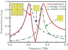
For the TE polarization, where the electric field is parallel to the y-axis, the filter transmission characteristics at normal incidence are shown in Fig. 2 (see the solid line). Two resonance poles occur at 0.303 THz and 0.38 THz in a frequency range from 0.2 THz to 0.5 THz, which shows good agreement with the theoretical results of 0.3 THz and 0.375 THz. The maximum transmissions at these frequencies are 94.9% and 94.6%, respectively. In addition, the two different frequency selective surfaces are simulated, i.e., the single large cross and the single small cross (as shown in the insets to Fig. 2). All of the structures exhibit bandpass characteristics, while there is only one band for both the large and small cross structures: the large and small cross structures correspond to the first and second single band filters, respectively. Deployment of the two sizes of cross-shaped resonator together will result in a dual-band filter, which is caused by superposition of the bandpass filters (as shown by the solid line). Because of the coupling between the two resonators, the central frequency and the insertion loss of the dualband filter do not completely correspond to those quantities for the two single bands.
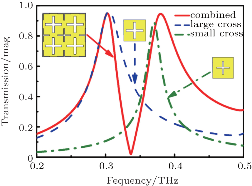 | Fig. 2. Numerical simulation results of transmission spectra at normal incidence for the three different configurations indicated in the insets. |
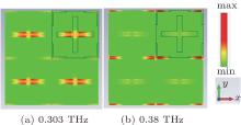
To further clarify the physical mechanisms of the dual-band structures, the electric field distributions of the 2 × 2 unit cells at the resonant frequencies of 0.303 THz and 0.38 THz are shown in Fig. 3. The color map indicates the relative local electric field amplitude, in which the electric field is parallel to the y-axis. For a unit cell (as indicated by the solid frame), the electric field resonance occurs in the large cross for the first resonant frequency of 0.303 THz, while it occurs in the small cross at 0.38 THz. Outside the two crosses, the electric field values are very weak. Therefore, the two pass bands arise from enhanced transmission assisted by the two cross resonances, where the first and second transmissions are associated with the electromagnetic resonances of the large and small crosses, respectively. As indicated in Eq. (1), the resonant frequency of the double-cross structure is inversely proportional to the cross-length L, which means that a longer cross will produce a lower resonance frequency.
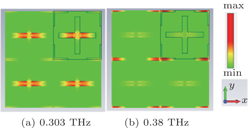 | Fig. 3. Electric field distributions at the resonant frequencies of (a) 0.303 THz, and (b) 0.38 THz. |
For practical applications, efficient filters are required not only to be insensitive to polarization but also to be insensitive to direction of incidence. Therefore, we also evaluate the dual-band filter performances at various angles of incidence. The simulated transmission rates as a function of frequency and angle of incidence for the TE and TM polarizations are shown in Fig. 4. The two red strips in each figure indicate the two angle-independent high pass-bands. Under both TE and TM polarizations, and for incident angles (θ ) of up to 30° , transmission of more than 92% is still obtained for each of the resonance peaks, although there is a slight red shift of the central frequency.
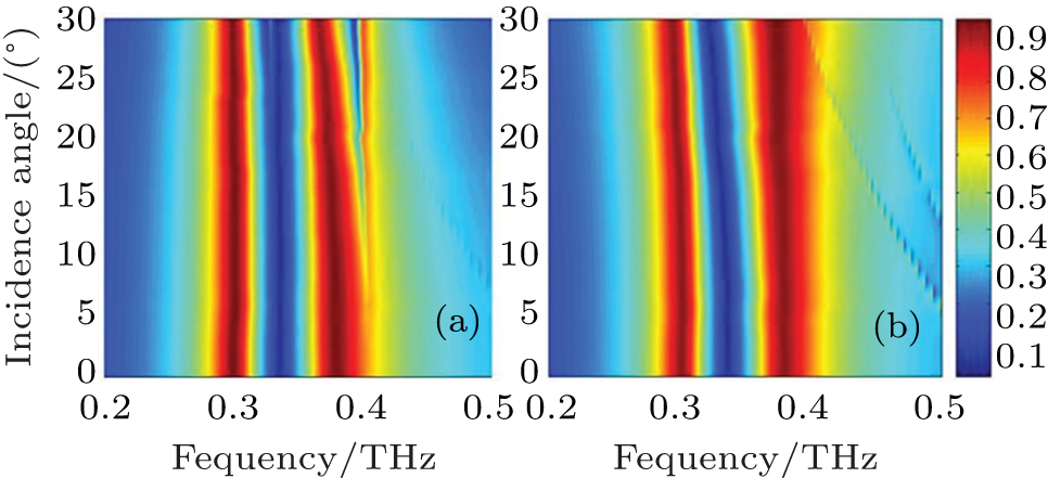 | Fig. 4. Simulated transmission efficiencies versus frequency and angle of incidence under (a) TE and (b) TM polarizations. |
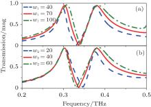
The characteristics of the dual-band filter actually depend on its geometrical parameters. Figure 5 shows the transmittance spectra for various values of the cross-lengths a and b, while the remaining parameters are fixed. As shown in Fig. 5(a), increasing the size of the large cross causes an obvious red shift in the transmission peaks in the first band and a smaller red shift in the second band, because the resonance frequency of the first band is mainly dependent on size a, i.e., f1 = c/2a. For a = 460, 500, and 540 μ m, the simulated transmission peaks are at 0.281, 0.303, and 0.325 THz, respectively, which are in good agreement with the calculated results of 0.278, 0.3, and 0.326 THz, respectively. However, both the peaks and the bandwidth of the first band increase because more waves near the resonant frequency can be transmitted through the filter with increasing a. In Fig. 5(b), the transmission peaks in the second band decrease with increasing b, because the resonance frequency is dependent on size b; i.e., f2 = c/2b. For b = 380, 400, and 420 μ m, the simulated transmission peaks are at 0.397, 0.38, and 0.364 THz, respectively, which are again in good agreement with the calculated results of 0.395, 0.375, and 0.357 THz, respectively. Figure 6 shows the transmittance spectra for various values of the cross-widths w1 and w2, while the remaining parameters are fixed. The results show that both the peaks and the bandwidths of the two bands increase with increasing cross-width, because more waves near the resonant frequencies can be transmitted through this structure, while the out-of-band rejection on one side of the two bands tends to decrease.
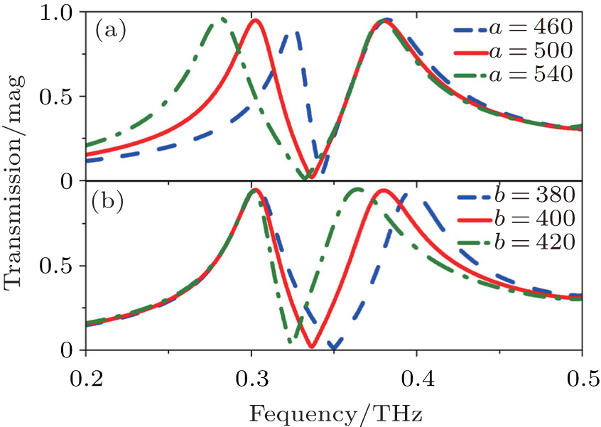 | Fig. 5. Variations of transmission of the dual-band filter with frequency for different cross-lengths: (a) large cross a, and (b) small cross b. |
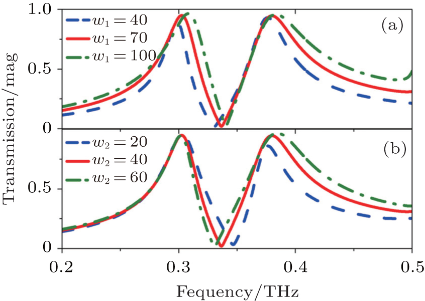 | Fig. 6. Variations of transmission with frequency of the dual-band filter for different cross-widths, (a) large cross w1, and (b) small cross w2. |
In this work, three samples are fabricated by perforating a 100-μ m-thick molybdenum layer with a periodic array of cross holes with a laser (LPKF ProtoMat S43). Table 1 shows the dimensions of the samples. Terahertz time-domain-spectroscopy (THz-TDS) was used to characterize the dual-band responses. The functional frequency region of THz-TDS is mainly determined by its optical setup, and is 0.2 THz– 2.5 THz in this case. The THz time-domain data R(t) and S(t), corresponding to the reference and sample spectra, respectively, were obtained by averaging the results of repeated measurements. After Fourier transformation of the THz time-domain data, the frequency-dependent complex transmission coefficient of the sample can be determined from the following equation:

where S(ω ) and R(ω ) are the time-domain data of the sample and reference spectra, respectively.
| Table 1. Geometric parameters of the dual-band filters (μ m). |
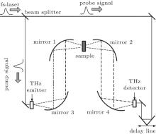
Figure 7 shows the diagram of the THz-TDS test system. In brief, the output of a mode-locked Ti-sapphire (Spectra Physics Mai Tai HP), with a pulse duration of 70 fs, central wavelength of 800 nm, and repetition rate of 82 MHz, is used to generate and detect the THz transient. The THz pulses are generated from a low-temperature growth GaAs photoconductive antenna, and a ZnTe crystal with (110) orientation is used as the THz wave detector. To fix the 100-micron-thick Mo filter for testing, a circular aperture is used. Figures 8(a) and 8(b) show the front view and back view of the aperture with a sample fixed in the center, respectively.
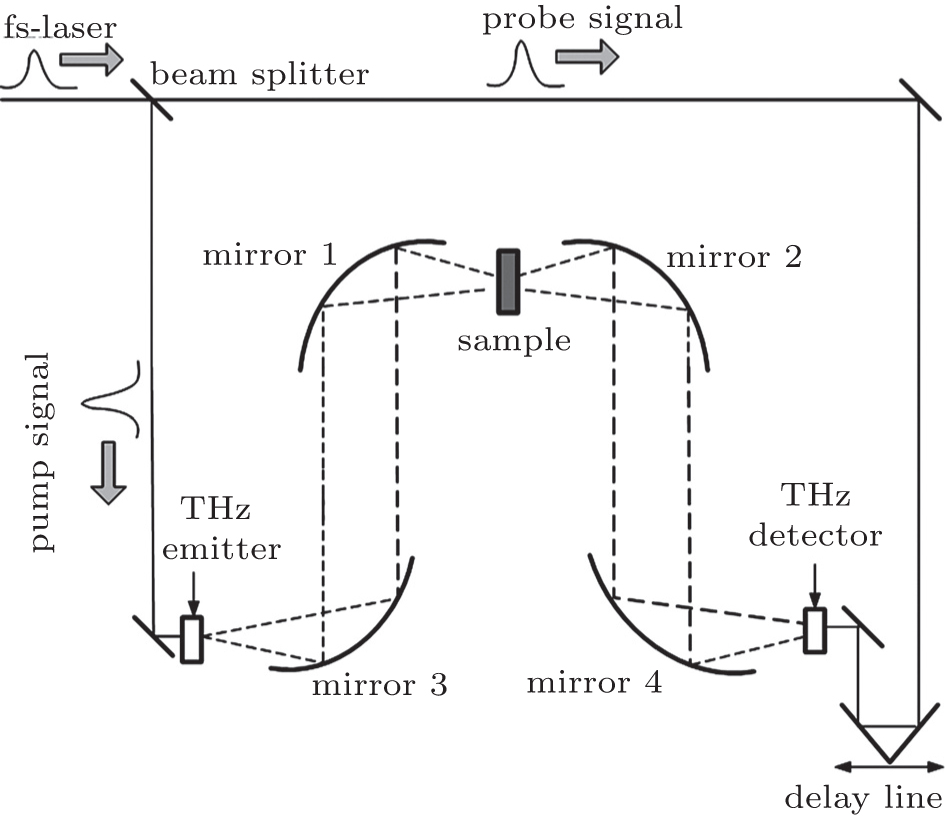 | Fig. 7. Diagram of the THz-TDS test system. |
 | Fig. 8. Circular aperture to fix the samples. |
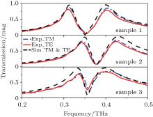
Figure 9 shows the THz wave transmittance characteristics of the three samples at frequencies ranging from 0.2 THz to 0.5 THz, where the dashed line represents the simulated results of both the TM and TE polarizations, the dash-dot and solid lines denote the measured results of the TM and TE polarization, respectively. It is seen that the radiation at normal incidence is nearly insensitive to polarization because of the rotational symmetry of the cross-shaped structures. Considering the TE polarization, the measured results of sample 1 show transmittance peaks of 81% at 0.312 THz and 78% at 0.403 THz, while the simulated results show transmittance peaks of 95% at both 0.314 THz and 0.401 THz. For sample 2 the measured results show transmittance peaks of 77% at 0.343 THz and 80% at 0.43 THz, while the simulated results show transmittance peaks of 95% at 0.35 THz and 97% at 0.43 THz. For sample 3, the measured results show transmittance peaks of 76% at 0.336 THz and 84% at 0.396 THz, while the simulated results show transmittance peaks of 96% at both 0.334 THz and 0.398 THz.
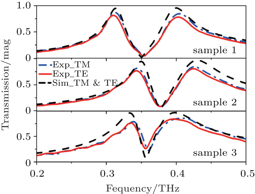 | Fig. 9. Experimental transmission spectra of the dual-band filters. |
The measured transmission curves match the simulated curves; however, there are slight shifts in the resonance frequency and lower transmission efficiency, which are caused by dimension error processing. Since the samples are not cleaned by an ultrasonic cleaner, dust in the holes may reduce the transmission magnitude The roughness of the sample surface may be another reason for the large transmission loss. Although metal roughness cannot be simulated in the CST software, it is well known metal roughness is inversely proportional to conductivity. By simulation, we find that the larger the conductivity, the higher the transmission of the filter is. Using metals with higher conductivity will then increase the transmissions of the two bands. In addition, the periodic boundary conditions approximate an infinite array in the simulations, while the experimental results are measured with limited periods (see Fig. 8), this discrepancy will also affect the results.
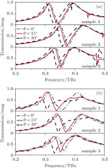
For oblique incidence angles ranging from 0° to 30° , figures 10(a) and 10(b) show the simulated and measured transmission magnitudes of the three samples at the TM polarization. The results of the TE polarization are not achieved as we cannot rotate the sample to the orthogonal direction due to the limitation of the experiment setup. It is observed that the experimental results exhibit the same behaviors as those from simulations. When the incident angle is further increased, their dual resonant modes shift to the lower frequencies, which is accompanied with a reduction in the transmission.
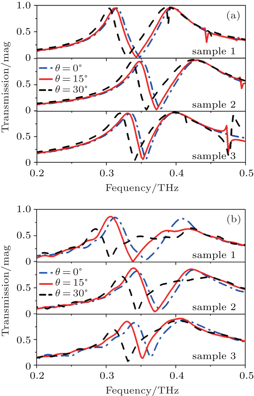 | Fig. 10. Transmission spectra of the dual-band filters with oblique incidence: (a) simulations, (b) experiments. |
In this work, we design and fabricate dual-band filters by using a laser to perforate a molybdenum layer with double cross-shaped slots. The transmission characteristics of the filters are measured using THz-TDS in a range of 0.2 THz– 0.5 THz. The encouraging results provided by the designed filter include polarization insensitivity at normal incidence simple fabrication with low cost, good selectivity performance, both in the lower and higher bands, due to the weak coupling between the two neighboring cross slots. These properties may lead to potential applications in dual-band sensors, THz communication systems, and other emerging THz technologies.
| 1 |
|
| 2 |
|
| 3 |
|
| 4 |
|
| 5 |
|
| 6 |
|
| 7 |
|
| 8 |
|
| 9 |
|
| 10 |
|
| 11 |
|
| 12 |
|
| 13 |
|
| 14 |
|
| 15 |
|
| 16 |
|
| 17 |
|
| 18 |
|
| 19 |
|
| 20 |
|
| 21 |
|