Multifunctional disk device for optical switch and temperature sensor
[Bian Zhen-Yu, Liang Rui-Sheng† , Zhang Yu-Jing, Yi Li-Xuan, Lai Gen, Zhao Rui-Tong]
, Zhang Yu-Jing, Yi Li-Xuan, Lai Gen, Zhao Rui-Tong]
 |


†Corresponding author. E-mail: liangrs@scnu.edu.cn
*Project supported by the National Natural Science Foundation of China (Grant Nos. 61275059 and 61307062).
A multifunctional surface plasmon polariton disk device coupled by two metal–insulator–metal (MIM) waveguides is proposed and investigated numerically with finite-difference time-domain simulation. It can be used as optical switch and temperature sensor by filling disk with liquid crystal and ethanol, respectively. The simulation results demonstrate that the transmission characteristics of an optical switch can be manipulated by adjusting the radius of disk and the slit width between disk and MIM waveguides. The transmittance and modulation depth of optical switch at 1550 nm are up to 64.82% and 17.70 dB, respectively. As a temperature sensor, its figure of merit can reach 30.46. In this paper, an optical switch with better efficiency and a temperature sensor with better sensitivity can be achieved.
Surface plasmon polaritons (short as SPPs) are the electromagnetic surface waves trapped on the surfaces of metals that travel along the interface between metal and insulator. SPPs are very promising for applications in miniaturized optical devices due to their ability to overcome the diffraction limit of light in traditional optics. In the recent years, a lot of subwavelength optical waveguide devices based on SPPs have been proposed, such as Mach– Zehnder in-ter-fero-me-ters, [1] splitters, [2] Bragg reflectors, [3] sensors, [4] Y-shaped combiners, [5] optical amplifier, [6] wavelength demultiplexing structure, [7] filters based on tooth-shaped resonator, [8] ring resonator, [9] and nanodisk resonator.[10] In the SPP research field, optical switches[11, 12] and sensors are also popular topics. Zhu et al. designed an optical switch based on double teeth-shaped structure at telecom wavelengths, [13] Chen et al. proposed another optical switch based on asymmetric double-ring resonator resonance.[14] Although they all used liquid crystal (LC) as the active medium, the transmittance and modulation depth were not good enough. So far, the figure of merit (FOM) of localized surface plasmon resonance (LSPR) sensor based on Fano resonance has achieved 3.8 for a coupled dipole– quadrupole antenna[15] and 5.7 for a gold disk heptamer.[16] However, the value of FOM is still too small. To the best of our knowledge, there is no report on a structure to realize the function of both optical switches and sensors.
In this paper, we propose a multifunctional disk device coupled by two metal– insulator– metal (MIM) waveguides, which is used as an optical switch and a temperature sensor by filling the disk with LC and ethanol, respectively. When the LC is filled in the disk, the transmittance and modulation depth of the proposed optical switch are larger than those of other structures.[13, 14] A temperature sensor with better sensitivity and greater FOM than LSPR sensors[15, 16] can be obtained when ethanol is filled in the disk.
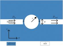
The schematic diagram of a multifunctional disk device is shown in Fig. 1. Two slits are symmetrically placed on both sides of the disk. The insulator between the slit and the disk is air (nd = 1). The metal is assumed to be silver, whose complex relative permittivity can be characterized by the well-known Drude model[17]

where ɛ ∞ = 3.7 is the dielectric constant at the infinite frequency; ω p = 9.1 eV, γ = 0.018 eV: γ and ω p are the electron collision frequency and bulk plasma frequency, respectively; and, ω is the angular frequency of the incident wavelength. TM-polarized plane wave propagates from left to right side of the waveguide. The Pin and Pout represent the powers at incident and transmitted ports, respectively. The transmittance is defined as T = Pout/Pin.[9]
 | Fig. 1. Schematic diagram of a multifunctional disk device. |
When the incident wave transmits from input waveguide to output waveguide, part of the incident wave is reflected to the input waveguide and the other part of the wave is coupled into the disk segment. Once the resonance condition is satisfied, a stable standing wave in the disk will form. The resonant condition can be given by solving the following equation[18]

where kd = k(ɛ d)1/2 and km = k(ɛ m)1/2 are the wave vectors in the dielectric disk and metal, with ɛ d and ɛ m are the relative permittivities of dielectric and metal, respectively; r is the radius of the disk; Jn and 


where ω is the frequency of incident light, ω 0 represents the resonance frequency, 1/τ i and 1/τ w denote the decay rate of the field induced by the internal loss in the cavity and the power escape through the waveguides, respectively. The resonance will form when the resonant condition is satisfied. Based on Eq. (3), the resonance peak transmittance Tmax = (1/τ w)2/(1/τ w 1/τ i)2 is almost equal to 1 when 1/τ i is much less than 1/τ w. We can find that the transmission spectra around the resonant modes exhibit Lorentzian profiles.
When the disk is filled with LC, the device can be used as an optical switch. We select Merck BL009 mixture as the filled LC material. The reason for this is that the LC material is well studied and easy to obtain. The common refractive index of LC is 1.592. When the voltage is applied, the refractive index of LC will turn to 1.81. This characteristic of LC is called voltage-dependent birefringence.[21] The parameters of the optical switch are r = 360 nm, w = 50 nm, and d = 7 nm. We utilize the finite-difference time-domain (FDTD) method to simulate the transmission characteristics. The grid sizes in the x and z directions are set to 5 nm× 5 nm.
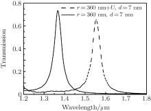
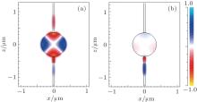
Figure 2 shows the transmission spectra of the optical switch. With an applied voltage, the wavelength of 1550 nm passes through output guide, whose transmittance is near 65%. This corresponds to the on-state of the optical switch. If we remove the voltage, then the wave of 1366 nm can pass through the output waveguide, while the wave of 1550 nm is almost completely reflected. The transmittance of 1550 nm is 1.10%, which corresponds to the off-state of optical switch. The contour profiles of fields ❘ Hz❘ at 1550 nm shown in Figs. 3(a) and 3(b) correspond to the on- and off-states of an optical switch, respectively. This clearly indicates that the wavelength of 1550 nm can pass through the optical switch with applied voltage, which corresponds to the on-state. On the contrary, the wavelength of 1550 nm cannot pass through the switch without applied voltage, which corresponds to the off-state.
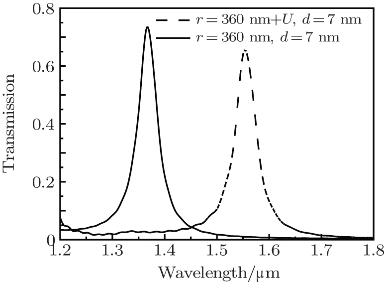 | Fig. 2. Transmission spectra of optical switch with and without applied voltage. The structural parameters of switch are r = 360 nm, w = 50 nm, d = 7 nm. |
 | Fig. 3. Contour profiles of the fields ❘ Hz❘ at 1550 nm (a) with and (b) without applied voltage. |
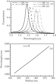
The transmission spectra of LC disk versus radius with applied voltage are shown in Fig. 4(a). It is obvious that the resonance wavelength has a red-shift with the increase of radius. Figure 4(b) shows that the resonant wavelength is proportional to the radius of disk. So it can allow different wavelengths to go through the switch by changing the radius of disk.
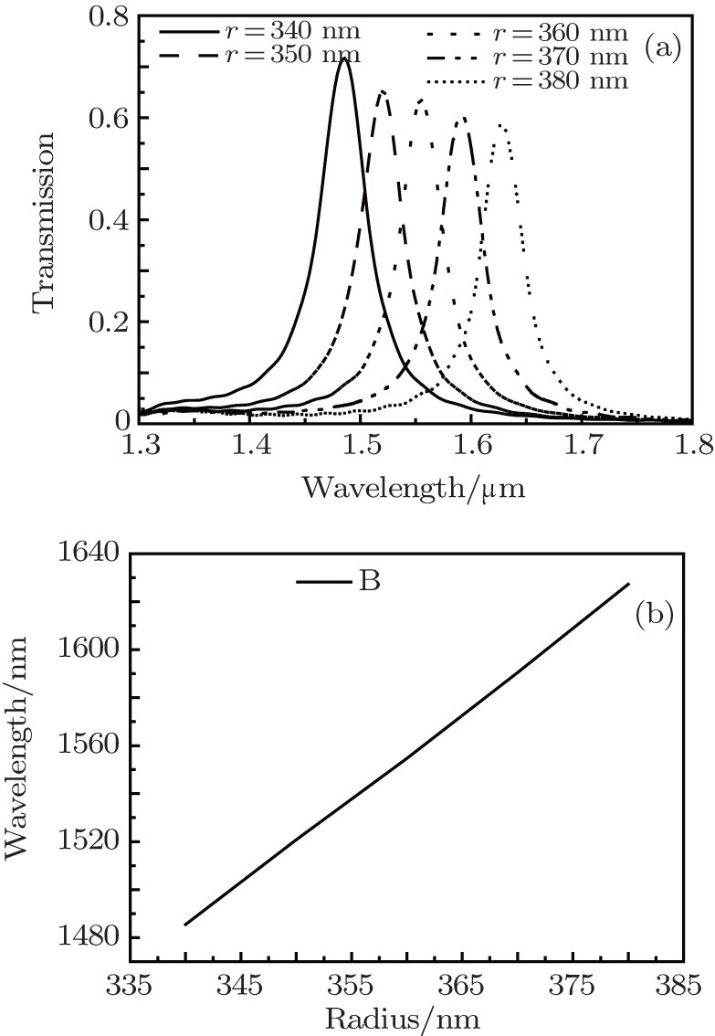 | Fig. 4. (a) The transmission spectra of LC disk versus radius with applied voltage, d = 7 nm and w = 50 nm. (b) The peaks of the transmission spectrum versus the radius of disk. |
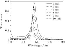
Next, we turn to study the transmittances for different slit widths between waveguides and disk. Figure 5 shows the transmission spectra for different slit widths with applied voltage. We can see that both the peak of transmittance and the full width at half maximum(FWHM) of the resonance spectrum decrease as the slit width increases. Considering the influence of transmittance and FWHM, we choose the slit width to be 7 nm. When the slit width is 7 nm, the maximum transmittance is 64.82% and the FWHM is 45 nm. The modulation depth of optical switch is defined as the logarithm of ratio of transmittance in on-state to that in off-state, i.e., Ms = 10log 10 (T1/T0), where T1 and T0 denote the transmittances of on-state and off-state, respectively. So the modulation depth of this optical switch is 17.70 dB based on Fig. 2. Compared with the double teeth-shaped structure at telecom wavelengths, [13] our structure has higher transmittance. Compared with asymmetric double-ring structure, [14] our structure has not only higher transmittance but also greater modulation depth.
 | Fig. 5. Transmission spectra of LC versus slit width with applied voltage. The other parameters are the same as those in Fig. 2. |
When the disk is filled with ethanol, the device can be designed as a high sensitive temperature sensor. The temperature coefficient of ethanol is 3.94× 10− 4, the refractive index of ethanol can be expressed as[22]

where T0 is the normal temperature of 20 ° C, T is the ambient temperature. Equation (4) indicates that the refractive index of ethanol is linear with respect to temperature T. The melting point and boiling point of ethanol are − 114.3 ° C and 78 ° C, so the device filled with ethanol is appropriate to work as a low temperature sensor.
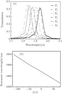
We investigate the influence of temperature T on the transmission spectrum. As shown in Fig. 6(a), the transmission spectra for different values of temperature T each exhibit a blue shift with the increase of temperature T. The resonant wavelength is inversely proportional to temperature T, which can be seen in Fig. 6(b). As temperature T increases, the refractive index of the disk decreases with the increase of temperature T, which leads to the blue shift of resonant wavelength. So we can calculate the changes of temperature and refractive index based on the shift of transmission spectrum. This is the principle of the temperature sensor. According to Eq. (4), when T = − 114.3 ° C and T = 78 ° C, the refractive indexes of disk are 1.4133942 and 1.337628, respectively. The transmission spectra at T = − 114.3 ° C and T = 78 ° C are shown in Fig. 6(a). It can be found that the resonant wavelengths are 1938.24 nm and 1834.69 nm, respectively. The temperature sensitivity of the sensor, which is defined as dλ /d T, is 0.54 nm/° C, and the refractive index sensitivity is defined as dλ /d n is 1366.70 nm RIU− 1. In order to account for the influence of the peak width on the sensing performance, the FOM, [23] which is defined as the refractive index sensitivity divided by FWHM, is used to measure the sensitivity of the sensing performance. The FOM is more reliable than refractive index sensitivity in the evaluation of sensors. The FWHMs of different transmission spectra are all almost equal to 44.87 nm in Fig. 6(a), consequently the value of FOM for this sensor is 30.46. The FOM of our sensor is greater than that of the LSPR sensor.[15, 16] Furthermore, our device can eliminate the influence of stress and strain on sensing.
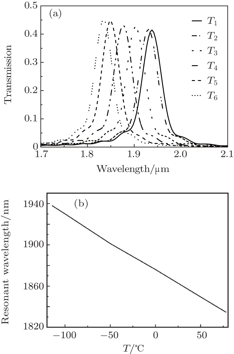 | Fig. 6. (a) Transmission spectra versus temperature T, where T1 = − 114.3 ° C, T2 = − 100 ° C, T3 = − 50 ° C, T4 = 0 ° C, T5 = 50 ° C, T6 = 78 ° C, r = 360 nm, w = 50 nm, and d = 7 nm. (b) The resonance wavelength of the structure versus temperature T. |
In this paper, a multifunctional disk device is proposed and numerically investigated with the FDTD method. We fill the disk with LC to realize the function of an optical switch. By applying a voltage or not, we can control the wavelength of 1550 nm to pass or to be reflected black. We are able to control different wavelengths to pass through switch with high transmittance by changing the radius of the disk and the slit width. A temperature sensor with high refractive index sensitivity and greater FOM can be obtained if the disk is filled with ethanol. Our device has potential applications in highly integrated optical switches and sensors due to its simplicity and compact size.
| 1 |
|
| 2 |
|
| 3 |
|
| 4 |
|
| 5 |
|
| 6 |
|
| 7 |
|
| 8 |
|
| 9 |
|
| 10 |
|
| 11 |
|
| 12 |
|
| 13 |
|
| 14 |
|
| 15 |
|
| 16 |
|
| 17 |
|
| 18 |
|
| 19 |
|
| 20 |
|
| 21 |
|
| 22 |
|
| 23 |
|