


An optical fiber spool for laser stabilization with reduced acceleration sensitivity to 10−12/g
[Hu Yong-Qia), b) , Dong Jinga), b) , Huang Jun-Chaoa), b) , Li Tang†a)  , Liu Liang‡
a) ]
, Liu Liang‡]
|
|


†Corresponding author. E-mail: litang@siom.ac.cn
‡Corresponding author. E-mail: liang.liu@siom.ac.cn
*Project supported by the National Natural Science Foundation of China (Grant Nos. 11034008 and 11274324) and the Key Research Program of the Chinese Academy of Sciences (Grant No. KJZD-EW-W02).
Environmental vibration causes mechanical deformation in optical fibers, which induces excess frequency noise in fiber-stabilized lasers. In order to solve such a problem, we propose an ultralow acceleration sensitivity fiber spool with symmetrically mounted structure. By numerical analysis with the finite element method, we obtain the optimal geometry parameters of the spool with which the horizontal and vertical acceleration sensitivity can be reduced to 3.25 × 10⁻¹²/g and 5.38 × 10⁻¹²/g respectively. Moreover, the structure features the insensitivity to the variation of geometry parameters, which will minimize the influence from numerical simulation error and manufacture tolerance.
Lasers with sub-hertz linewidths play key roles in the field of precision measurement science, such as optical atomic clocks, [1– 3] ultralow phase noise microwave generation, [4] high-resolution spectroscopy, [5] gravitational wave detection, [6] and precision tests of relativity.[7] As the traditional method to achieve ultranarrow-linewidth lasers, a highly isolated Fabry– Perot (F– P) cavity is utilized to suppress the frequency noises of lasers by the Pound– Drever– Hall technique.[8, 9] However, this powerful method requires tight alignment of free space optical elements, precise polarization adjustment, and spatial mode matching. To circumvent these problems, a radical alternative is to use an all-fiber-based interferometer as a frequency reference for laser stabilization.[10, 11] In contrast to traditional rigid cavity methods, the fiber-stabilized laser has a simple structure and requires no optical alignment while it has larger frequency drift. The frequency drift is due to the larger temperature coefficient of optical fiber and can be improved by some methods such as active temperature stabilization, more thermal shields or temperature feedforward technique.[12] Recently, a fiber-stabilized laser (FSL) with 0.67-Hz linewidth was demonstrated by Dong et al. in their latest published work.[13]
At low Fourier frequency, mechanical vibration induced frequency noise is dominated in an FSL. Environmental vibration causes mechanical deformations in the fiber which induce phase fluctuations and then convert into excess frequency noise to the lasers. Therefore, the spool which supports the fiber plays a critical role in this frequency noise conversion. In the field of optoelectronics oscillators (OEOs), such a problem has already been explored.[14– 18] The first report on low vibration sensitivity fiber spool was presented by Huang et al.[14] who developed an optical fiber spool with an acceleration sensitivity of ∼ 10− 10/g. Recently, Li et al.[19] proposed a new optical fiber spool with asymmetric support structure. Using the finite element method (FEM) simulation, the vertical (the direction perpendicular to the spooling plane) acceleration sensitivity exhibits linear dependence on a vertical geometry parameter and can be zeroed with optimized geometry parameters. It means that one has a possibility to obtain zero vertical acceleration sensitivity of the optical fiber spool if the “ zero point” can be exactly found. In practice, due to the large sensitivity slope, however, it is difficult to approach to this “ zero point” due to the unavoidable FEM simulation error and machining error. Moreover, this model cannot maintain low acceleration sensitivity in the horizontal (the direction in the spooling plane) and vertical directions simultaneously (this will be analyzed and discussed in the next context).
In this paper, we propose to design an optical fiber spool with ultralow acceleration sensitivity, which is not sensitive to the geometry parameters. The FEM is utilized to perform a detailed numerical analysis of various spool geometry parameters and to identify the optimal designs with improved acceleration immunity. We show that the spool can achieve acceleration sensitivities of ∼ 10− 12/g in both the horizontal and vertical directions over a range of geometry parameters.
As shown in Fig. 1, for an FSL system, the heterodyne arm-unbalanced Michelson interferometer acts as a frequency discriminator to convert the frequency fluctuation δ ν of the laser into the phase fluctuation δ φ of the heterodyne detected RF signal. Its transfer function[11] can be presented as

where f is the Fourier frequency, τ = 2nL/c is the unbalance time delay of the interferometer, L is the fiber length difference between two arms, n is the effective refractive index, and c is the speed of light in a vacuum. At low frequencies (f ≪ 1/τ ), the magnitude of the transfer function is approximately equal to 2π τ . For an FSL, consequently, the acceleration sensitivity can be further defined as

where a is the acceleration variation in units of g; ν is optical frequency; Δ L, Δ τ , and Δ ν are the acceleration-induced fiber length variation, variation of delay time, and frequency fluctuation respectively.
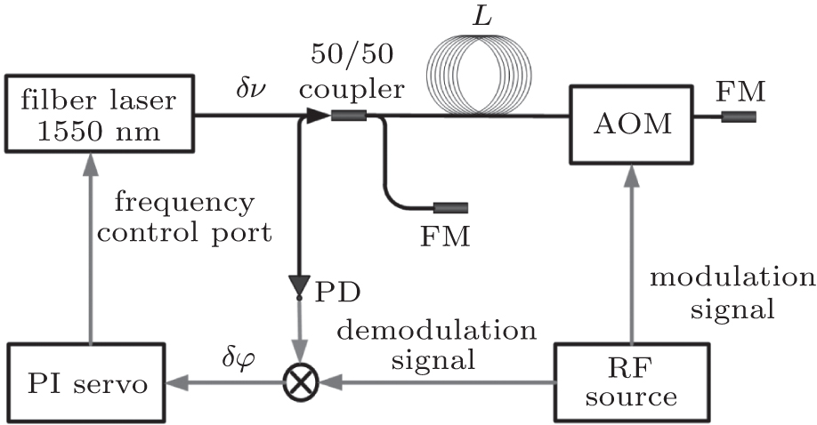 | Fig. 1. Principle of laser stabilization by fiber delay line. AOM: acousto-optical modulator, FM: Faraday mirror, PD: photodiode, PI: proportional integral, RF: radio frequency. |
By tightly winding the optical fiber onto a fiber spool, the fiber length variation will follow the surface deformation of the spool.[19] With precisely spooling the optical fiber and proper winding tension, this hypothesis is applicable and the acceleration sensitivity can be related to the surface deformation of the spool by

where S is the initial surface area of fiber spool, Δ S is the variation of the surface area induced by acceleration, and Sf is the surface area under acceleration. It implies that we need to extract the surface variation from the FEM simulation data. This operation requires processing the coordinates of the deformed nodes to recalculate the area.
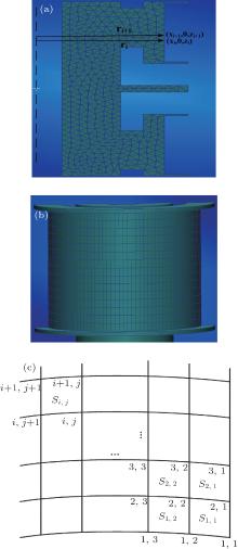
For fiber winding consideration, the spool is designed as an axisymmetric structure and the symmetry axis is perpendicular to the spooling plane. When the force is applied along the axis, the surface deformation is also axisymmetric. Therefore, for vertical acceleration sensitivity calculation, the spool can be modeled as two-dimensional (2D) elements (see Fig. 2(a)) and the surface area is simplified into

where ri = xi is the radius of node (xi, 0, zi), Δ zi = zi+ 1 – zi is the vertical distance between node (xi, 0, zi) and (xi+ 1, 0, zi+ 1). Note that in the FEM modeling of this paper, the coordinate z is the symmetry axis of the spool.
As the acceleration direction is parallel to the spooling plane, there exists no axisymmetric deformation and a three-dimensional (3D) model (see Fig. 2(b)) must be used for horizontal calculation. We mesh the surface of the spool with quadrilateral elements (see Fig. 2(c)), and the surface area is given by

where Δ zi, j = zi+ 1, j – zi, j is the vertical distance between node (xi, j, yi, j, zi, j) and (xi+ 1, j, yi+ 1, j, zi+ 1, j), li, j is the arc length between node (xi, j, yi, j, zi, j) and (xi, j+ 1, yi, j+ 1, zi, j+ 1) and can be calculated from

The selection of the mesh element is critical to FEM simulation and we perform calculations to check the relations between the calculated area and the type and size of element. Compared with the F– P cavity modeling which requires fine meshing only in a few critical areas, [20] the fiber spool requires ultrafine meshing on the entire spool surface and this increases the number of elements. To increase the resolution while maintaining a reasonable number of elements, we use a variable meshing approach that the surface undergoes fine meshing whereas the bulk is coarser. In practice, for the 3D model, the surface element size is 1.5 mm while the bulk element size is 3 mm. When the 2D model is used, the surface element size can decrease to 0.6 mm.
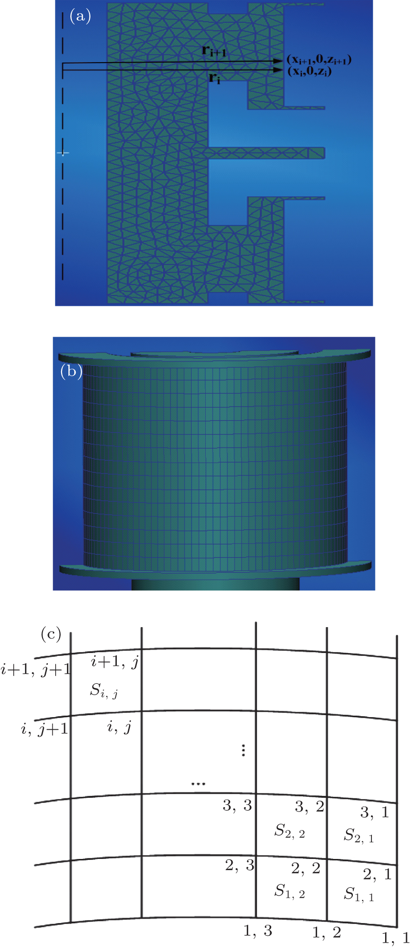 | Fig. 2. FEM meshing style of (a) 2D model and (b) 3D model, and (c) its surface area calculation schematics. |
Normally, the frequency of mechanical vibration ranges from a few hertz to several hundred hertz. It implies that the wavelength of propagating sound wave induced by the mechanical vibration is much larger than the dimension of the fiber spool, meaning that all particles move in phase inside each eigenmode.[20] Therefore, at low frequency, the dynamic analysis can be substituted by the static analysis. In the calculation, we exert a gravity-like force of 1000 g on the spool with the direction either in the vertical or horizontal plane. The supporting plane of the spool is restricted in a certain manner to prevent the model from moving translationally and rotationally.
Our simulation is based on Hooke’ s law, which implies that the deformation of the spool is linear with respect and proportional to the stress applied to it. For a rigid spool, this assumption is applicable. The material of the spool is chosen to be titanium because of its stiffness and small mass compared with other metal materials. Similar work on other spool materials has also been done and published.[16]
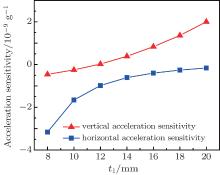
Prior to introducing the new spool, it is necessary to analyze both the vertical and horizontal acceleration sensitivities of Li et al.’ s model (see Fig. 3(a)) which is not mentioned in their report.[19] Its geometry schematics is shown in Fig. 3(b). In the calculation, we find there exist geometry parameters, such as t1 and t3, to which both the vertical and horizontal acceleration sensitivities are sensitive. Figure 4 shows the FEM calculated variations of vertical and horizontal acceleration sensitivities with parameter t1. To simplify the calculation, we fix the radius r and the parameter t2 and all other geometry parameters are fixed at optimized values. At the vertical acceleration sensitivity “ zero point” , the horizontal acceleration sensitivity is about 1 × 10− 9/g. As t1 increases, the horizontal acceleration sensitivity is reduced to the level near zero while vertical acceleration sensitivity increases rapidly. It means that we cannot achieve ultralow acceleration sensitivity both in the vertical and horizontal directions at the same time. The defect of Li et al.’ s model is that there are many parameters which have an effect on the vertical acceleration sensitivity and it is difficult to optimize them independently.
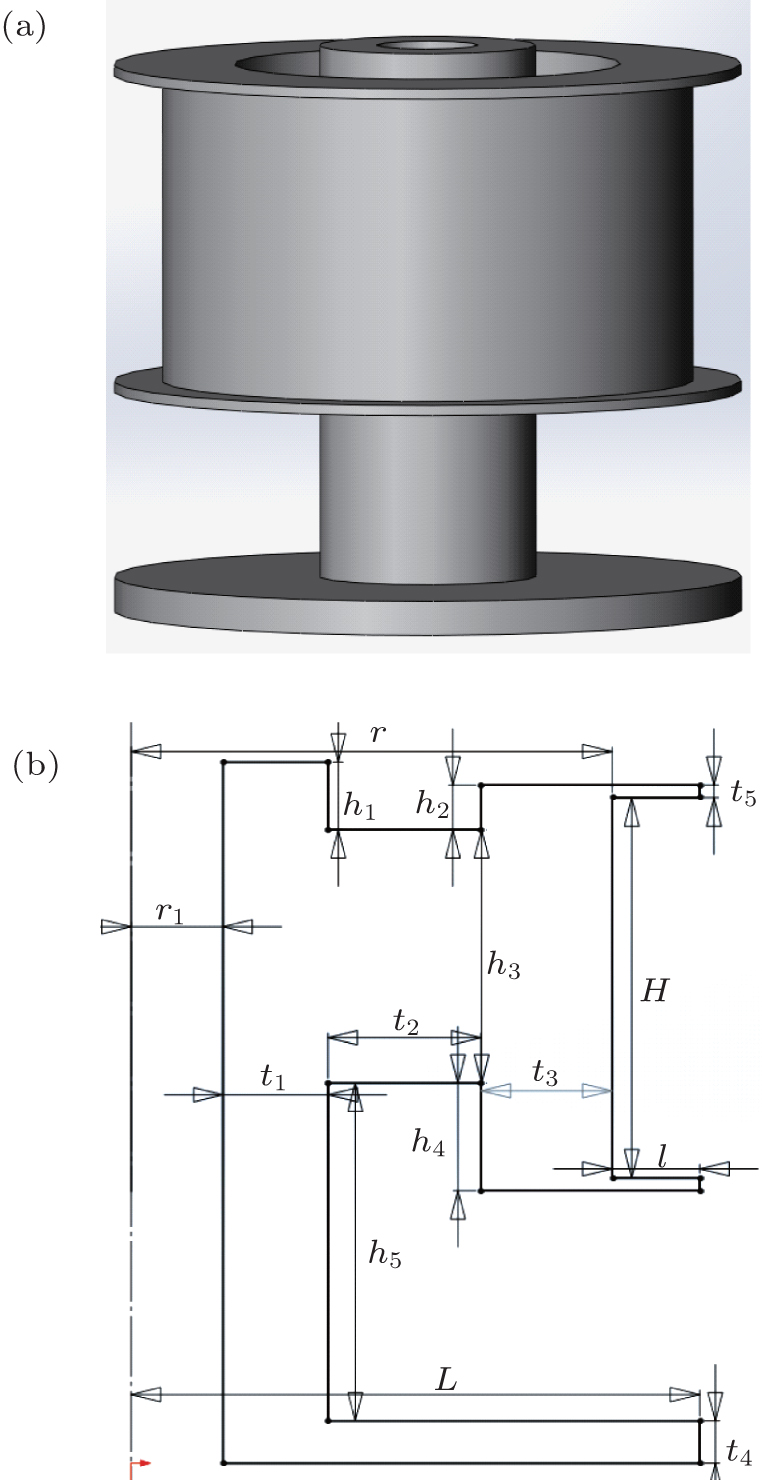 | Fig. 3. (a) The optical fiber spool published in Ref. [19] and (b) its geometry schematics. |
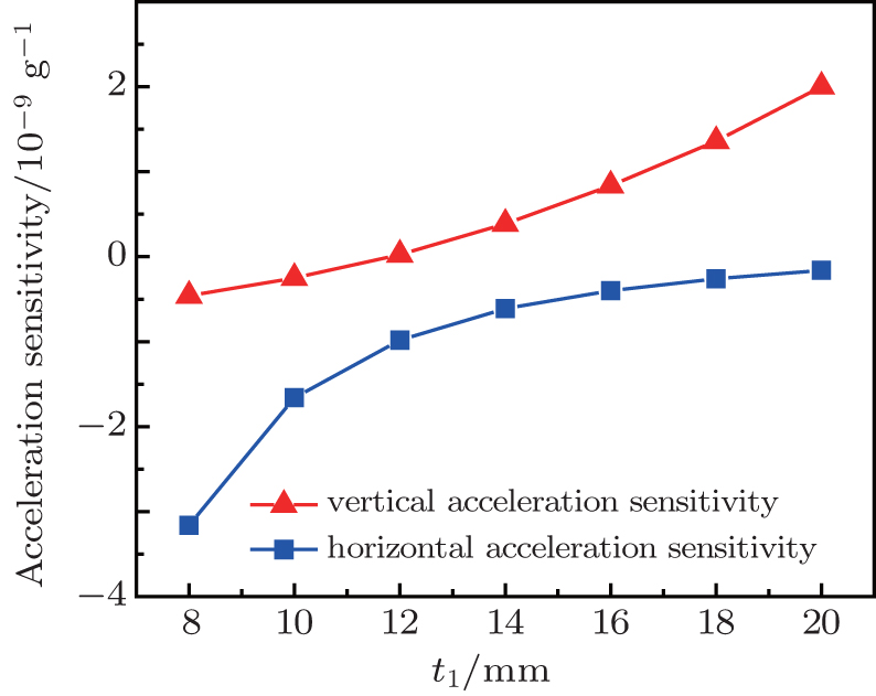 | Fig. 4. Vertical (upper) and horizontal (lower) acceleration sensitivities versus t1, FEM calculated by Li et al.’ s model. |
In order to solve such a problem, we propose an optical fiber spool with symmetrically mounted structure (SMS) (see Figs. 5(a) and 5(b)). The optical fibers are wound on the top and bottom cylinder surface respectively and need to be spliced into one. The mounting positions of the SMS spool are on the central plate and the “ top spool” is symmetrical with respect to the “ bottom spool” . Under vertical acceleration, the “ top spool” and the “ bottom spool” are subjected to equal but opposite forces. Consequently, they deform with the same quantity whereas the opposite sign results in zero deformation for the total spool, leading to a cancellation of vertical acceleration sensitivity. Additionally, according to this configuration, we can choose the geometry parameters of the spool to achieve ultralow horizontal acceleration sensitivity without substantially degrading the vertical acceleration resistance.
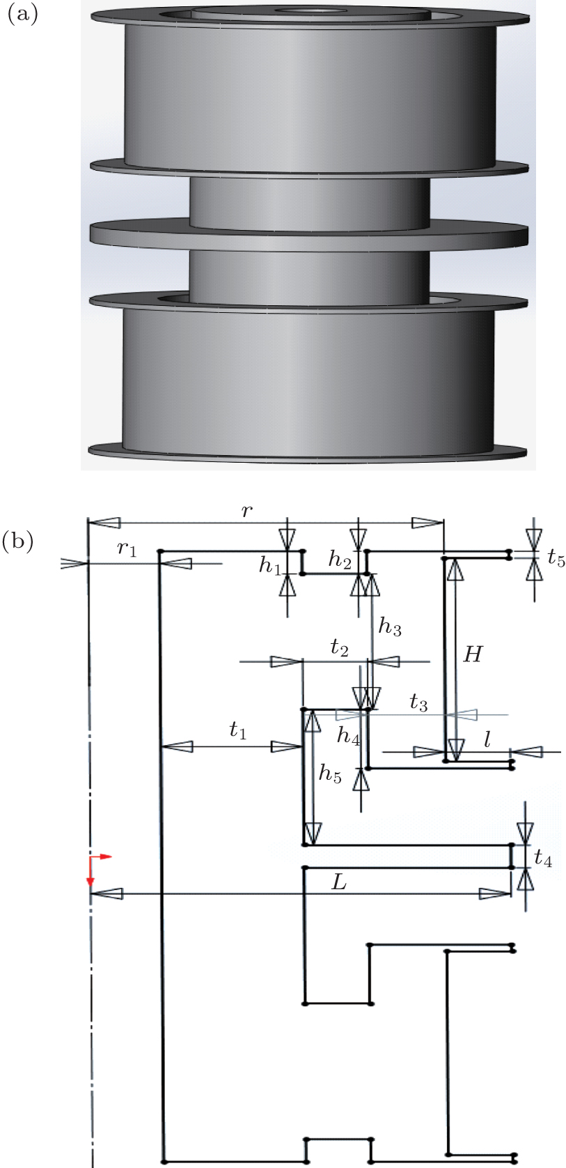 | Fig. 5. (a) Optical fiber spool with symmetrically mounted structure and (b) its geometry schematics. |
To verify the vertical acceleration sensitivity cancellation of the SMS spool, we construct a similar configuration with two identical Li et al.’ s spools (Fig. 6(a)). The two spools are mounted on the support symmetrically in the opposite direction and the optical fibers are spliced in series. We measure the vertical acceleration sensitivities of this configuration and a single spool. The preliminary results are shown in Fig. 6(b). Compared with the vertical acceleration sensitivity of a single spool, the vertical acceleration sensitivity of two symmetrically mounted spools is approximately one order lower which means that the symmetrically mounted structure is effective for acceleration sensitivity cancellation.
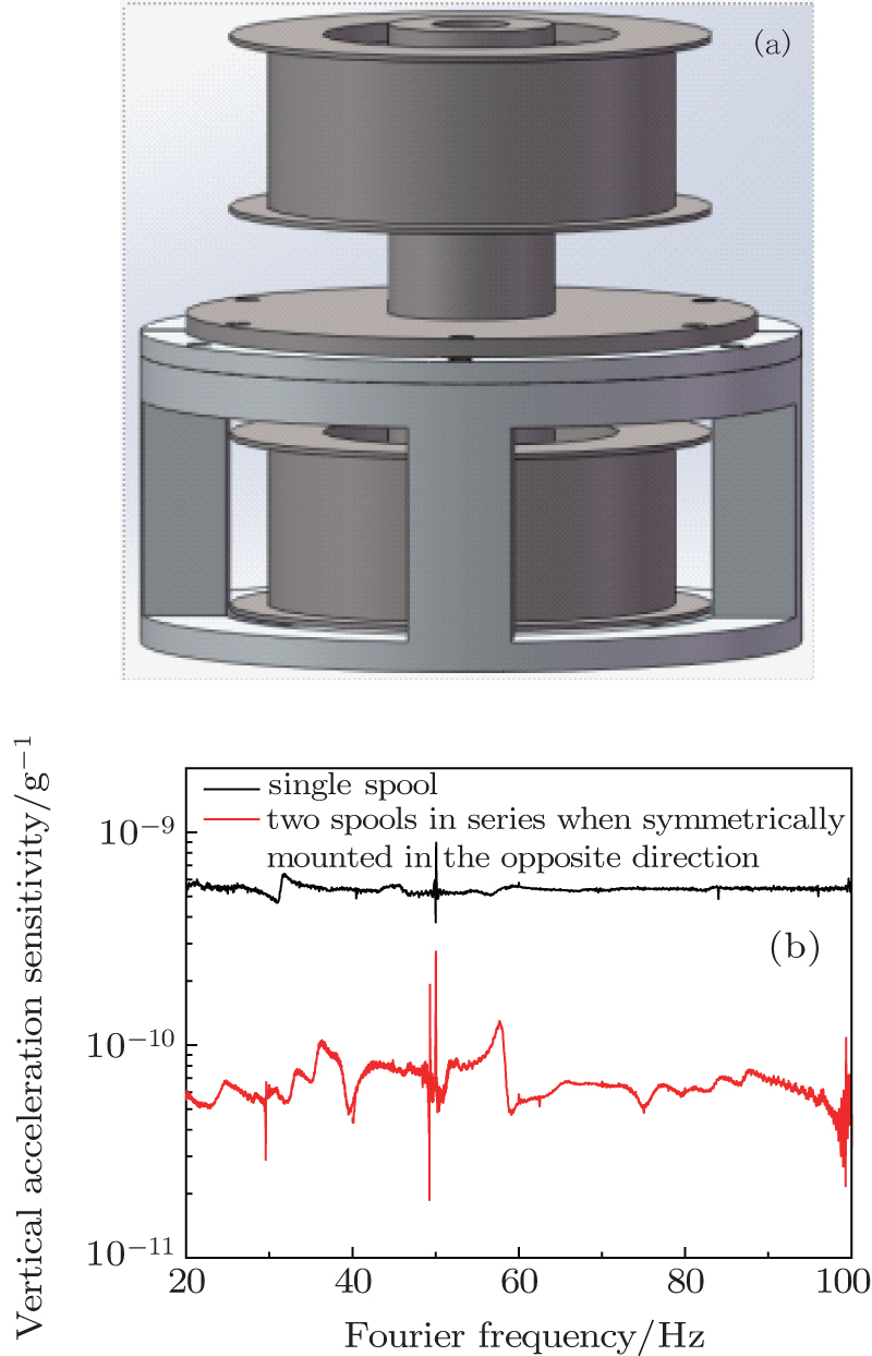 | Fig. 6. (a) The configuration of two symmetrically mounted spools, (b) the vertical acceleration sensitivities versus Fourier frequency of a single spool (black line (upper)) and two spools in series when symmetrically mounted in the opposite direction (red line (lower)). |
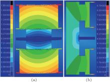
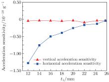
Figures 7(a) and 7(b) show the deformations of the SMS spool under horizontal and vertical forces respectively. To reduce the calculation complexity, we introduce some definitions as follows: (i) two variables h and t1; (ii) h = h1 = h2; (iii) the parameters r1, r, H, L, l, h3, h5, t2, t4, and t5 are fixed; (iv) h4 varies with h and t3 varies with t1. Fixing the value of h, the acceleration sensitivity of SMS spool is calculated with various t1 values. The results are shown in Fig. 8. As the parameter t1 increases from 12 mm to 26 mm, the horizontal acceleration sensitivity decreases and approaches to zero while the vertical acceleration sensitivity maintains a level below 1 × 10− 11/g. It means that ultralow acceleration sensitivities both in the vertical and horizontal directions can be obtained on the SMS spool.
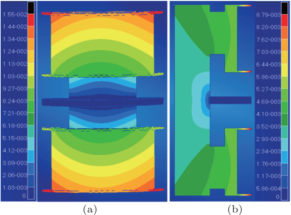 | Fig. 7. Deformation fringes of the SMS spool under (a) horizontal force and (b) vertical force (in units of millimeter). |
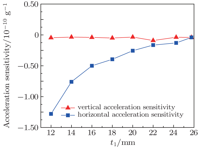 | Fig. 8. FEM calculated vertical (upper) and horizontal (lower) acceleration sensitivities of the SMS spool versus t1. |
In order to further optimize the geometry parameters, we calculate the acceleration sensitivities with different values of h and t1. The calculation results are shown in Figs. 9(a) and 9(b). To compromise the acceleration sensitivity and its dependence on the variation of the geometry parameters, h = 5 mm and t1 = 25 mm are the optimal values, with which we can achieve the acceleration sensitivities of 3.25 × 10− 12/g in the horizontal direction and 5.38 × 10− 12/g in the vertical direction. Especially, with the varying values of h and t1, the vertical acceleration sensitivity still remains a level lower than 8 × 10− 12/g. Meanwhile, in the horizontal plane, we find that an acceleration sensitivity below 2.5 × 10− 11/g can still be achieved when h and t1 vary over a range of 1.5 mm. Consequently, ultralow acceleration sensitivity is attainable despite a moderate geometry variation arising from the machining process or FEM simulation error.
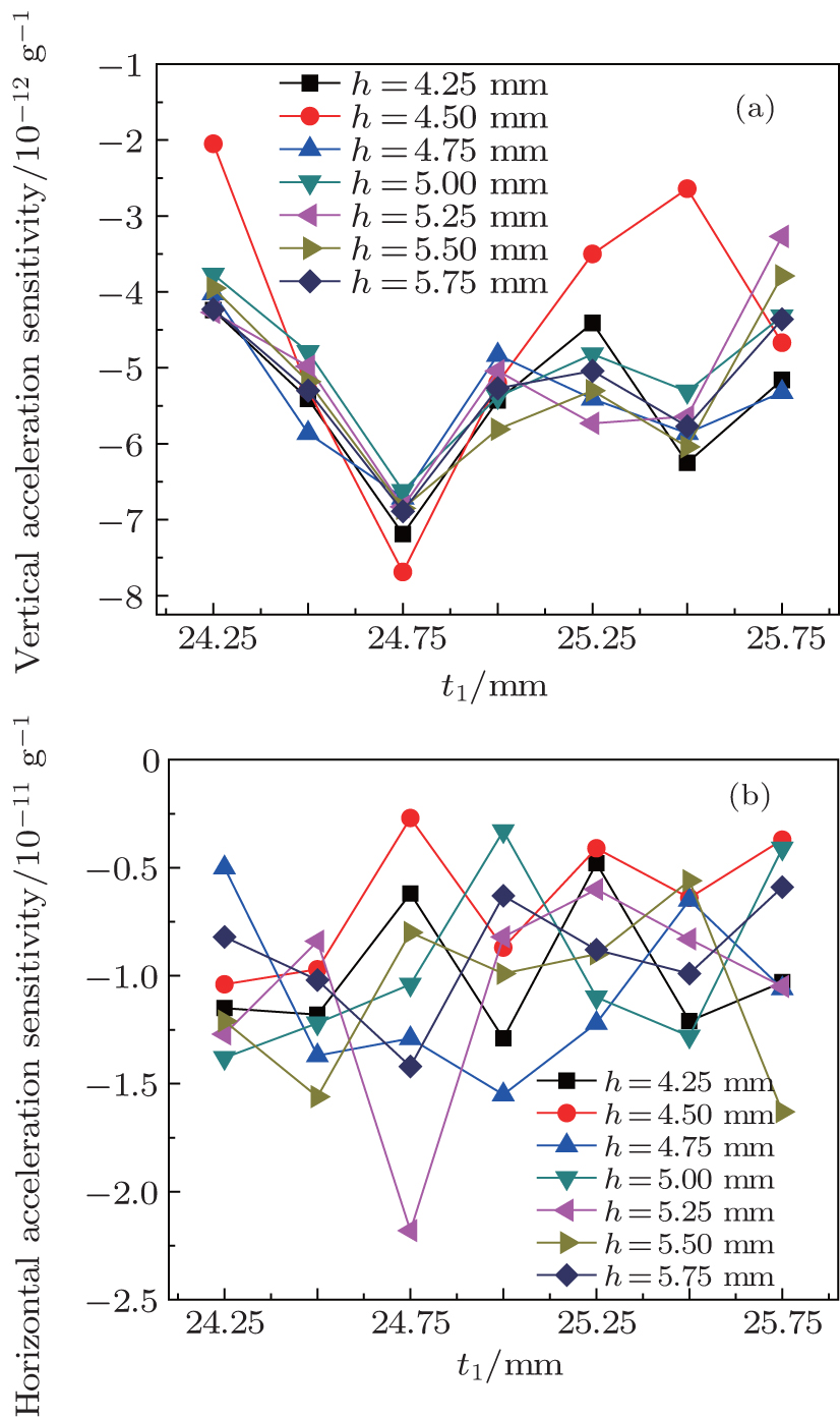 | Fig. 9. FEM calculated (a) vertical and (b) horizontal acceleration sensitivities of the SMS spool versus t1 for different h values. |
However, the vertical symmetry of the spool is extremely important for the cancellation of acceleration sensitivity and the machining tolerance which can potentially undermine the symmetry should be taken into account. For the worst consideration, when the parameters h and t1 of the “ top spool” differ from those of the “ bottom spool” by 0.1 mm (accumulated tolerance), the horizontal acceleration sensitivity will change from 3.25 × 10− 12/g to 1.26 × 10− 11/g while the vertical acceleration sensitivity will change from 5.38 × 10− 12/g to 1.55 × 10− 11/g. Therefore, to achieve an acceleration sensitivity of ∼ 10− 12/g, the attention must be paid to the machining tolerance of the vertical symmetry. Finally, a modal analysis is also performed and the first resonance is around 4 kHz.
In this paper, FEM is used to analyze the acceleration sensitivity of the optical fiber spool for laser stabilization. We use a 3D model for the horizontal analysis and a 2D model for the vertical analysis. To achieve the ultralow horizontal acceleration sensitivity and further reduce the dependence of vertical acceleration sensitivity on geometry parameters, we propose an optical fiber spool with symmetrically mounted structure. By FEM simulations, we obtain the optimal geometry parameters of the spool with which the horizontal and vertical acceleration sensitivities are minimized to 3.25 × 10− 12/g and 5.38 × 10− 12/g respectively. Additionally, the structure shows insensitivity to the variation of geometry parameters, which is useful when FEM simulation error and manufacture tolerance are unavoidable. By using such a fiber spool for laser stabilization, the vibration-induced frequency noise will be dramatically reduced and a few hundreds of a millihertz or even narrower linewidth can be expected to have no extra vibration isolation. From the extensive view, besides laser stabilization, the optical fiber spool discussed in this paper can be adopted, perhaps some modifications, by various applications such as the OEOs and optical fiber gyroscopes.
We would like to thank Santarelli G for his constructive suggestions.
| 1 |
|
| 2 |
|
| 3 |
|
| 4 |
|
| 5 |
|
| 6 |
|
| 7 |
|
| 8 |
|
| 9 |
|
| 10 |
|
| 11 |
|
| 12 |
|
| 13 |
|
| 14 |
|
| 15 |
|
| 16 |
|
| 17 |
|
| 18 |
|
| 19 |
|
| 20 |
|