Arbitrary frequency stabilization of a diode laser based on visual Labview PID VI and sound card output
Feng Guo-Sheng, Wu Ji-Zhou†

, Wang Xiao-Feng, Zheng Ning-Xuan, Li Yu-Qing, Ma Jie‡
, Xiao Lian-Tuan, Jia Suo-Tang
State Key Laboratory of Quantum Optics and Quantum Optics Devices, Instiute of Laser Spectroscopy, College of Physics and Electronics Engineering, Shanxi University, Taiyuan 030006, China
†Corresponding author. E-mail: wujz@sxu.edu.cn
‡Corresponding author. E-mail: mj@sxu.edu.cn
*Project supported by the National Basic Research Program of China (Grant No. 2012CB921603), the Program for Changjiang Scholars and Innovative Research Team in University of Ministry of Education of China (Grant No. IRT13076), the Major Research Plan of the National Natural Science Foundation of China (Grant No. 91436108), the National Natural Science Foundation of China (Grant Nos. 61378014, 61308023, 61378015, and 11434007), the Fund for Fostering Talents in Basic Science of the National Natural Science Foundation of China (Grant No. J1103210), the New Teacher Fund of the Ministry of Education of China (Grant No. 20131401120012), and the Natural Science Foundation for Young Scientists of Shanxi Province, China (Grant No. 2013021005-1).
1.IntroductionDiode lasers have been widely applied to many research fields, such as laser cooling, [1, 2] quantum information processing, [3] and precision measurement.[4– 7] Extended cavity geometries[8] provide easily tunable single-longitudinal-mode operation with short-term drift (on a millisecond time scale) stability at the ∼ 1-MHz level. Due to the frequency of diode laser being relatively sensitive to temperature and current, the long-term drift (on a time scale from seconds to minutes) is rather large: its typical value is 100 MHz or more.[9, 10] The precision experiments often require the longer-term frequency stabilization at a level of several MHzs, and an additional feedback is necessary. An available method is to employ the saturated absorption spectroscopy to stabilize the laser frequency to an atomic or molecular resonant transition. However, this technique can only be carried out at a few specific frequencies, not an arbitrary frequency.[11– 14] The acousto– optic modulator (AOM) has been extendedly used to shift the locked frequency to different values, but it is limited to a narrow responding frequency range of several hundred MHzs.
The rapid advances in ultracold atomic and molecular physics, e.g., the optical Feshbach resonance[15, 16] and the stimulated Raman photoassociation, [17, 18] have strongly necessitated the laser frequency to be locked to some particular frequencies rather than the atomic or molecular inherent transition frequencies. A feasible method is to employ a frequency chain as a two-step scheme, [19, 20] in which the frequency of the diode laser is locked to a stable reference cavity, when the cavity frequency is locked to an atomic or molecular transition. However, the high quality cavity and the controllable frequency shifter are very expensive and difficult to adjust.
Recently, an arbitrary frequency stabilization method[21] has been reported, in which the frequencies of Ti:sapphire and dye laser are locked with a drift of 40 MHz/h by a computer-controlled feedback system based on a program of lab-used windows 8. In this paper, we develop an arbitrary frequency stabilization method based on a freely available Labview Proportional-Integral-Derivative (PID) VI and sound card output. The error signal, induced from the difference between the frequency measured by a high-precision wavelength meter and the preset target frequency, is fed back to the piezoelectric transducer (PZT) module of a diode laser. The drift of 8 MHz within 25 min for an arbitrary target frequency is obtained by the PID VI.
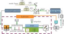
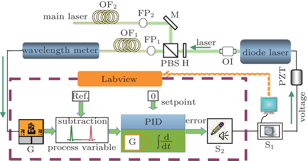
2.Experimental setupThe experimental setup is schematically depicted in Fig. 1. A home-made tunable grating feedback diode laser is used in our experiment with a central wavelength of 780 nm. The diode laser frequency can be tuned by changing the voltage used to control the PZT module. The absolute frequency of the diode laser is measured by a wavelength meter (HighFinesse-Angstrom, WS/7R) with a relative accuracy of 3 MHz, and its reading speed is limited to 1.45 MHz/s for a wavelength range from 370 nm to 1100 nm. The laser output is guided by a multimode fiber and input to the wavelength meter. The frequency is measured and displayed on the computer screen through the wavelength meter software. Simultaneously, the frequency is read in our Labview procedure by introducing a library function corresponding to the wavelength meter.
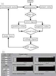
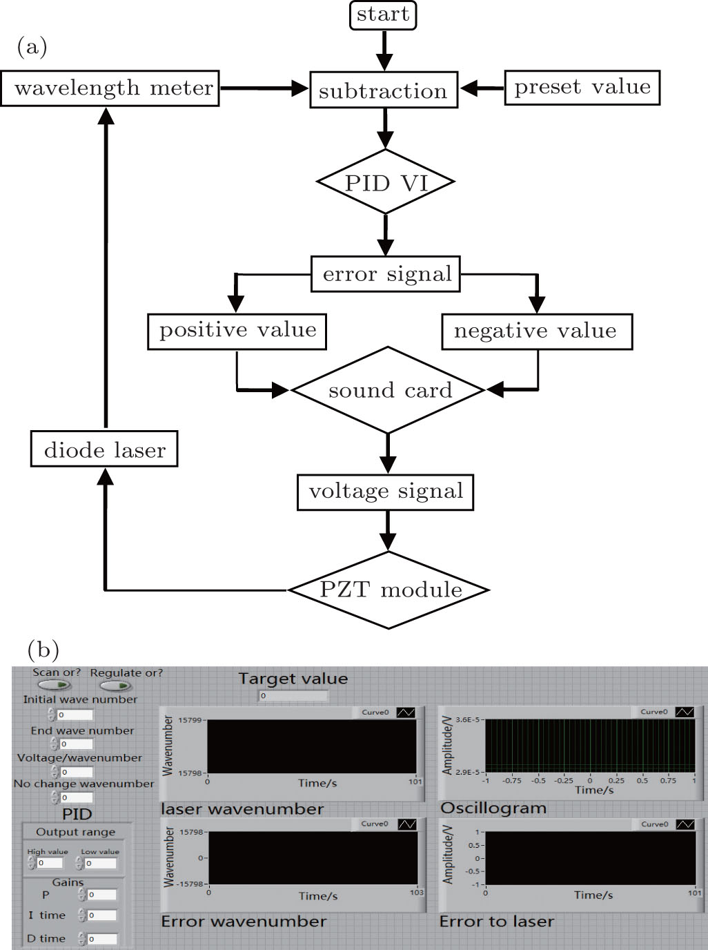
For stabilizing the diode laser frequency, a visual Labview procedure containing several VI modules is designed to realize the feedback system. The flow chart of the feedback system is shown in Fig. 2(a). When the Labview procedure starts to run, the diode laser frequency is recorded and shown in the waveform chart on our Labview interface as shown in Fig. 2(b). The subtraction is performed between the target frequency which is necessary to preset in the Labview procedure and the measured frequency, and this difference in frequency is sent to the input port of PID VI. Here we give a zero set-point which is compared with the input value of PID VI. If the difference between the laser frequency and the target frequency is zero, the output of PID VI will keep a constant voltage which is applied to the PZT module. When there is a little difference between the measured laser frequency and the target frequency, the integrator switches on immediately, so that we can stabilize the frequency of the diode laser to a preset target frequency. The choice for negative or positive feedback of error signal is presented, making it possible to directly apply this feedback system to many kinds of diode lasers. With the support of the Labview VI modules, the sound card is used to take the place of the data acquisition card, which is added to transfer the continuous digital error signal to an analog voltage signal, then the resulting signal is fed to a high voltage amplifier circuit to control the PZT module. After several feedback loops, the frequency of diode laser is stabilized to the preset target value.
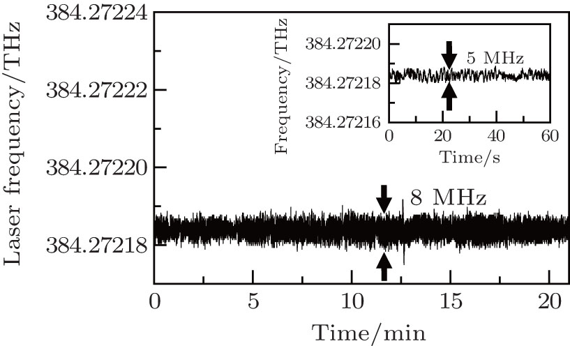
3.Experimental resultsFigure 3 shows the time evolution of the laser frequency locked by our feedback system. We preset the absolute target frequency of 384.272184-THz while tuning the laser frequency to a value near the desired frequency by the scanning offset used to adjust the grating. Consequently, the laser frequency is driven to the same value as the preset target frequency via the feedback system. For a short-time locking, we obtain a minimum frequency drift of 5 MHz as shown in the inset of Fig. 3. There is a little increase in the frequency drift when the control system runs for longer time over 21 min, and the drift is about 8 MHz.
Comparing with the frequency drift of ∼ 1 MHz induced by locking the frequency of the diode laser to the atomic and molecular transitions, our scheme gives a robust method to obtain a relatively large frequency drift but for an arbitrary frequency. This large frequency drift mainly comes from the relative accuracy of 3 MHz and the limited reading speed of the wavelength meter. In addition, the intrinsic frequency drift of the wavelength meter is easily induced by the variation of the environmental temperature.
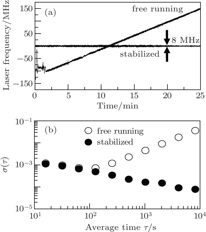
In Fig. 4, we compare the frequency drift of the diode laser that is locked by our developed feedback system with the drift of the free-running diode laser. Figure 4(a) shows that the frequency drift of the free-running diode laser increases linearly with time increasing. The frequency drift rate is about 11 MHz/min. Besides, the frequency of the free-running diode laser has a random mode hopping, which can be caused by the drift of temperature and other influences such as external tiny vibrations. When the frequency of the diode laser is locked to the preset target frequency by our scheme, the frequency drift is reduced to 8 MHz within 25 min. This illustrates that our scheme is very effective to stabilize the diode laser to an arbitrary frequency. The line-width of the diode laser is about 1 MHz and keeps unchanged. The reading of the wavelength meter would drift after about 25 min under laboratory conditions, so it needs to be repeatedly calibrated by an He– Ne laser before running the feedback system. In our experiment, for verifying the result of the locking frequency, we place the wavelength meter in an airtight environment, therefore long-term frequency stabilization over about 3 h is achieved. Figure 4(b) shows the Allen variance σ (τ ) which can be used to describe the frequency stability of the locked diode laser.[13, 22] Allan variance is defined as

where σ (τ ) is derived from the error of the function of τ , and ȳ i represents the average value of the laser frequency in the i-th divided based on average time. The stabilized laser frequency has the distinctly low σ (τ ) in a long average time, with a minimum value of σ (τ ) = 7.72 × 10− 5. Next, it should be promising to reach the small laser frequency drift by building an appropriate insulator box and a temperature-controlled wavelength meter.
4.ConclusionsIn this work, we demonstrate that the frequency of a diode laser is stabilized to an arbitrary frequency based on an available Labview PID VI and sound card output with the help of a high-precision wavelength meter. Compared with the frequency drift ∼ 280 MHz of the free-running diode laser, the frequency drift of the locked diode laser is reduced to 8 MHz within 25 min. Our frequency locking system has several advantages. First, the diode laser can be locked to an arbitrary frequency by inputting a preset target frequency only. Second, a simple locking and feedback system consists of a freely available Labview PID VI and the sound card with a rather low price. Finally, this method can be adapted to realize the arbitrary frequency stabilization for many other kinds of lasers.


