
Exploring electromagnetic response of tellurium dielectric resonator metamaterial at the infrared wavelengths
[Song Jia-Kun, Song Yu-Zhi, Li Kang-Wen, Zhang Zu-Yin, Xu Yun, Wei Xin, Song Guo-Feng† ]
]
]
 |


†Corresponding author. E-mail: sgf@semi.ac.cn
*Project supported by the National Basic Research Program of China (Grant Nos. 2011CBA00608, 2012CB619203, 2015CB351902, and 2015CB932402), the National Key Research Program of China (Grant No. 2011ZX01015-001), and the National Natural Science Foundation of China (Grant Nos. 61036010, 61177070, 11374295, and U1431231).
We numerically investigate the electromagnetic properties of tellurium dielectric resonator metamaterial at the infrared wavelengths. The transmission spectra, effective permittivity and permeability of the periodic tellurium metamaterial structure are investigated in detail. The linewidth of the structure in the direction of magnetic field W x has effects on the position and strength of the electric resonance and magnetic resonance modes. With appropriately optimizing the geometric dimensions of the designed structure, the proposed tellurium metamaterial structure can provide electric resonance mode and high order magnetic resonance mode in the same frequency band. This would be helpful to analyze and design low-loss negative refraction index metamaterials at the infrared wavelengths.
The study of metamaterials has received much attenuation for the ability to manipulate the electromagnetic waves at will. Metamaterials as man-made nanostructures have many novel optical properties, such as negative refraction, [1, 2] perfect absorption, [3] and invisibility cloaking.[4] Most of the scientific research about metamaterials is based on metallic nanostructures.[5, 6] As has been demonstrated, the electric resonance and magnetic resonance wavelengths could be tuned by the geometric parameters of the structure arbitrarily.[7] A variety of metallic nanostructures has been designed to obtain the negative refractive index with appropriate geometric dimensions.[6– 8] The main reasons for restricting the application of metallic metamaterials are the inherent ohmic losses and the difficulty in integrating into bulk volumes. Compared with metallic metamaterials, the dielectric metamaterials are less material loss, invariant to the excitation angle and easy fabrication.[9] The basic electric or magnetic resonance based on the interaction between the electromagnetic waves and high refractive dielectric material was investigated.[10– 12] Compared with other dielectric materials, tellurium (Te) as dielectric resonance material has a large index of refraction and low loss in the infrared wavelength.[13, 14] Owing to the advantages mentioned above, Te dielectric metamaterial is a good candidate of metamaterial structure design for practical application. The basic magnetic magnetism of the Te dielectric resonator was theoretically and experimentally demonstrated in 2012 by Ginn et al..[15] In this paper, the optical parameters, effective permittivity, and permeability of the periodically arranged Te metamaterial structure are systematically investigated with different geometric dimensions. High order magnetic resonance modes are also studied. Through analyzing the transmission spectra of the periodic Te dielectric structure, the influence of the linewidth Wx in the direction of the magnetic field on the resonance modes is clearly demonstrated. The electric resonance and magnetic resonance wavelengths of the structure can be tuned by the geometric parameter Wx. With appropriate geometrical dimensions of the structure, the electric resonance and high order magnetic resonance modes can be tuned to the same optical frequency. We also show that the even-order magnetic resonance modes are excited in oblique incidence.
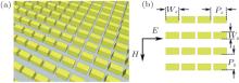
Figure 1(a) shows the tilted view of the single layer periodic arrangement Te metamaterial structure. The cuboid tellurium structure is periodically arrayed (Px = Py = P) in the x– y plane with geometrical parameters indicated in Fig. 1(b). The refractive index (n) and extinction coefficient (k) of Te dielectric material used in our simulation are cited from Ref. [10]. Transmission and reflection coefficients are calculated from a rigorously coupled wave analysis method with periodic boundary conditions.[16, 17] Through a retrieving procedure, the effective permittivity and permeability of our proposed structure are obtained.[18]
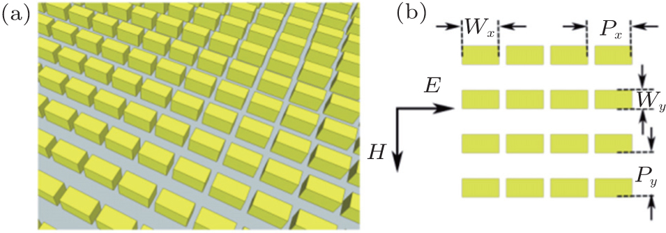 | Fig. 1. (a) Schematic diagram of the periodically arranged dielectric metamaterials structure. (b). Top-view of the structure with geometric parameters indicated. |
We fix the geometric parameters indicated in Fig. 1(b) with P = 3.4 μ m and Wy = 1.5μ m. The thickness of the Te dielectric layer is 1.8 μ m. Figure 2(a) shows the transmission spectra of the Te metamaterial structure with different values of linewidth Wx. The linewidth Wx of the cuboid Te structure has an effect on the position and the strength of the electric resonance and magnetic resonance modes. For the structure with Wx = 1.5 μ m, transmission spectrum is similar to the result reported in Ref. [11]. The transmission dips around 9.6 μ m and 7.5 μ m indicated by M1 and E1 are the lowest (magnetic resonance) and the second lowest (electric resonance) Mie resonances, respectively. With the increase of Wx ranging from 1.5 μ m to 3 μ m, the electric resonance and magnetic resonance modes shift to a longer wavelength as shown in Fig. 2(a). When Wx = 1.8 μ m, another transmission dip (high order magnetic resonance mode M3) indicated by the black arrow comes up and it also moves to a longer wavelength with the increase of Wx. As shown in the transmission spectra, the high order magnetic resonance (M3) and the electric resonance (E1) wavelengths increase with Wx and they overlap in the same frequency band when Wx = 3 μ m. The permittivity and permeability are simultaneously negative between 8.11 μ m and 8.56 μ m. The influence of the changing geometry parameter Wx on magnetic resonance and electric resonance modes can be further understood by analyzing the effective permeability and permittivity. Figures 2(b) and 2(c) show the values of effective permeability and permittivity with different values of linewidth Wx from which we can see the shifting of magnetic resonance (M3 and M1) and electric resonance (E1) wavelengths clearly. The positions of the magnetic resonance modes (M3 and M1) can be tuned by changing the linewidth Wx. The minimum value of permeability is indicated by the black dashed lines shown in Fig. 2(b). The minimum permeability value of the magnetic resonance mode M3 increases with Wx, while the minimum permeability value of the magnetic resonance mode M1 decreases. As we can see from Fig. 2(c), the minimum value of permittivity (black dashed line) increases with Wx and the effective permittivity property of the structure with Wx = 3 μ m differs from the others. A prominent and visible change is that the electric resonance (E1) strength of the structure with Wx = 3 μ m is greatly increased. This is because as the distance between adjacent Te dielectric structures decreases, the electromagnetic interaction between them is strengthened and this will be further validated with electromagnetic field analysis.
 | Fig. 2. (a) Transmission spectra of the proposed Te metamaterial structure with different values of linewidth Wx. Values of effective permeability (b) and permittivity (c) derived from the retrieved procedure with different values of linewidth Wx. The inset shows the real and imaginary parts of the effective permittivity of the stru1cture with Wx = 3 μ m. |
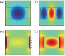
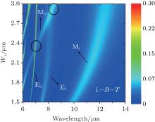
To clearly understand the magnetic resonance and electric resonance behaviors of the Te dielectric metamaterials structure, we plot the magnetic field and electric field distributions of the structure with Wx = 3 μ m at their respective resonance wavelengths. Figures 3(a) and 3(b) show the magnetic field (Hy) distributions of magnetic resonance modes M1 and M3 in the middle of the Te dielectric structure in the x– y plane. Most of the magnetic field is localized inside the cuboid Te dielectric structure. From the distributions of the magnetic field shown in Figs. 3(a) and 3(b), we can figure out that they are the first-order and third-order magnetic resonance modes. As shown in Fig. 3(c), we can see that most of the electric field (Ex) is localized in the region between the neighbor Te dielectric structures, other than the situation of the structure with Wx = 2.1 μ m shown in Fig. 3(b). This is because with the value of Wx increasing from 2.1 μ m to 3 μ m, the distance between adjacent Te dielectric structures decreases and the coupling strengthens. As a result, the electric resonance strength is considerably increased. The effects of geometric parameter Wx on electric resonance and magnetic resonance modes at normal incidence are illustrated in Fig. 4. As shown in the contour plot of 1– R– T (R and T denote reflectance and transmittance of the proposed structure, respectively), only the odd-order resonance modes can be excited at normal incidence. With changing the linewidth Wx of Te dielectric structure, the electric resonance and magnetic resonance modes shift to longer wavelengths. The electric resonance and magnetic resonance modes are overlapped with specific geometric dimensions, for example, M3 and E1 crossing at around 8.55 μ m with Wx = 3 μ m. Negative permittivity and negative permeability will be obtained in the same frequency band provided by the electric resonance and magnetic resonance modes. When the magnetic resonance mode and the electric resonance mode are tuned to the same frequency band, it would be helpful to realize all-angle negative refraction.[19]
 | Fig. 3. Computed electromagnetic field distributions of the first-order (a) and third-order (b) magnetic resonance modes. (c) The first-order electric resonance mode of the structure with Wx = 3 μ m. (d) The first-order electric resonance mode of the structure with Wx = 2.1 μ m. The arrows display the direction and magnitude of the electromagnetic field (magnetic field ((a), (b)) and electric field ((c), (d))) in the x– y plane. |
 | Fig. 4. Effects of geometric parameter Wx on the electric resonance and magnetic resonance modes. The black ellipses indicate the regions where the electric resonance and magnetic resonance modes overlap. |
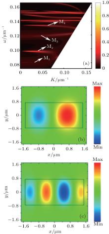
In the following simulation, we also investigate the resonance properties of the structure with Wx = 3 μ m at non-normal incidence. Figure 5(a) shows the calculated 1– R– T dispersion plot of the Te dielectric metamaterial structure in a wavenumber range from 0.0714 μ m− 1 to 0.167 μ m− 1. The peaks around 0.082 μ m− 1 and 0.118 μ m− 1 respectively are the first-order (M1) and the third-order (M3) magnetic resonance modes, which are nearly independent of the incident angle. The even-order magnetic resonance modes indicated by M2 and M4 also come up at non-normal incidence. At normal incidence, the even-order magnetic resonance modes are forbidden because there is no magnetic moment along the direction of the incidence magnetic field. At oblique incidence, the symmetry of anti-parallel magnetic field distribution is broken and a non-zero magnetic moment paralleling to the incidence magnetic field direction will be produced. Figures 5(b) and 5(c) show the electromagnetic field distributions of the second-order and fourth-order magnetic resonance modes with Wx = 3 μ m at an incident angle of 30° . The asymmetric anti-paralleling magnetic field distributions are clearly demonstrated.
 | Fig. 5. (a) Calculated 1– R– T dispersion plot as a function of transverse wave vector and wave number. Second-order (b) and fourth-order (c) magnetic resonance modes of the structure with Wx = 3 μ m at an incidence angle of 30° . |
In this paper, through investigating the transmission spectra and the retrieved parameters, we systematically analyze the electric resonance and magnetic resonance properties of the designed structure. As shown in this paper, the electric resonance and magnetic resonance wavelengths can be tuned by Wx. The magnetic resonance mode (M3) overlaps with the electric resonance mode (E1) at around 8.5 μ m with Wx = 3 μ m. This can be utilized to design low-loss negative refraction index metamaterial with negative permittivity and negative permeability simultaneously. As demonstrated with the dispersion curve, the magnetic resonance modes are nearly independent of the incidence angle which would be helpful to realize all-angle negative refraction. The even-order magnetic resonance modes are also excited at oblique incidence. The FOM value of the negative refraction metamaterial realized with Te dielectric material would be greatly increased due to the low internal absorption loss. The investigation of the electromagnetic properties of the Te dielectric metamaterial structure would be helpful to design low-loss bulk negative refraction index metamaterials.
| 1 |
|
| 2 |
|
| 3 |
|
| 4 |
|
| 5 |
|
| 6 |
|
| 7 |
|
| 8 |
|
| 9 |
|
| 10 |
|
| 11 |
|
| 12 |
|
| 13 |
|
| 14 |
|
| 15 |
|
| 16 |
|
| 17 |
|
| 18 |
|
| 19 |
|