
Reciprocity principle-based model for shielding effectiveness prediction of a rectangular cavity with a covered aperture
[Jiao Chong-Qing† , Li Yue-Yue]
, Li Yue-Yue]
|
|


†Corresponding author. E-mail: cqjiao@ncepu.edu.cn
*Project supported by the National Natural Science Foundation of China (Grant No. 51307055) and in part by the State Grid Corporation of China (Grant No. No. SGRI-WD-71-12-009).
According to the reciprocity principle, we propose an efficient model to compute the shielding effectiveness of a rectangular cavity with apertures covered by conductive sheet against an external incident electromagnetic wave. This problem is converted into another problem of solving the electromagnetic field leakage from the cavity when the cavity is excited by an electric dipole placed within it. By the combination of the unperturbed cavity field and the transfer impedance of the sheet, the tangential electric field distribution on the outer surface of the sheet is obtained. Then, the field distribution is regarded as an equivalent surface magnetic current source responsible for the leakage field. The validation of this model is verified by a comparison with the circuital model and the full-wave simulations. This time-saving model can deal with arbitrary aperture shape, various wave propagation and polarization directions, and the near-field effect.
Electromagnetic shielding is one of the primary technical measures for suppressing electromagnetic interference via a spatial field coupling channel. A cavity made of metallic material is frequently used as a shielding box for electromagnetic interference suppression. The shielding effectiveness (SE) of a shielding box may be reduced dramatically by apertures existing inevitably in its walls for some practical and indispensable requirements/functions.[1– 4] Sometimes, conductive gaskets or sheets are employed to close/load the apertures in order to improve the SE.[5– 9] The rapid development of material science and technology offers us more and more choices of conductive material with good flexibility and low weight for electromagnetic shielding applications.[10– 12] For this type of application, a noticeable problem is to determine the electromagnetic fields inside a box, resulting from the penetration of external electromagnetic waves through the covered apertures. In principle, this problem can be treated efficiently by various computational techniques.[13, 14] However, such methods are usually computationally time-consuming and require large amounts of computer memory space, especially for threedimensional (3D) geometries with electrically large size. As a result, analytical techniques, which are usually time-saving, have clear physical meaning, and are also easy to implement, are desirable. Towards this end, a kind of analytical technique, the intermediate level circuital model, has been presented.[5, 9] The circuital model is used to calculate the SE of a rectangular box with rectangular apertures covered by conductive sheets when illuminated by an incoming plane wave. In the circuital model, the electromagnetic penetration through the covered apertures is described by the transfer impedance of the sheets, and the box is considered as a rectangular waveguide with short-circuited termination and is modeled as a series of transmission lines. Each transmission line corresponds to an electromagnetic mode of the waveguide. The circuital model is reliable in terms of calculation accuracy and is fast as far as the computer running time is concerned. In addition, the involvement of numerous higher order modes makes this model applicable for the highly overmoded cavity. Despite the above advantages, the application range of this model is restricted greatly by two factors: 1) the shape of the aperture must be rectangular; 2) the source must be a plane wave with normal incidence. In principle, the circuital model can also be extended to handle different polarization and incidence angles by re-deducing the expression of the mode magnitude coefficient C, but this will complicate the derivation procedure greatly. However, the further extension of the circuital model towards including an arbitrary aperture shape will unavoidably require the use of a numerical integral to calculate the coefficients. Moreover, the numerical integral needs to be carried out one by one for each considered mode, which will increase the computer running time obviously when a number of modes have to be involved in the case of a highly overmoded cavity.
In this paper, by using the reciprocity principle, the problem of electromagnetic penetration into a box is converted into a problem of electromagnetic leakage from the box. By the combination of well-known knowledge including the Green’ s function of a rectangular cavity, the transfer impedance of a good conductor sheet, and the electromagnetic radiation from the surface magnetic current source, the new problem can be solved semi-analytically. In this model, the aforementioned limitations encountered in the circuital model are eliminated due to the use of a numerical integral to calculate the electromagnetic fields radiated from an equivalent surface magnetic current source. As a result, arbitrary aperture shape, various wave propagation and polarization directions, and near-field effect can be considered in the present model. For the present model, the use of numerical integral will not obviously increase the computer running time due to the fact that the integral only needs to be conducted once.
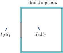
Figure 1 shows a shielding box with two electric dipoles placed inside and outside it, respectively. The external dipole has a moment of I1d l1, and the internal one has I2d l2. The E-field of a shielding box (SE) is usually defined as

where E0 and Es are the fields produced by the external dipole and are observed at the same point within the box, when the box is absent and present respectively. Since E0 is easily calculated, the key of obtaining SE is the determining of the penetration field Es.
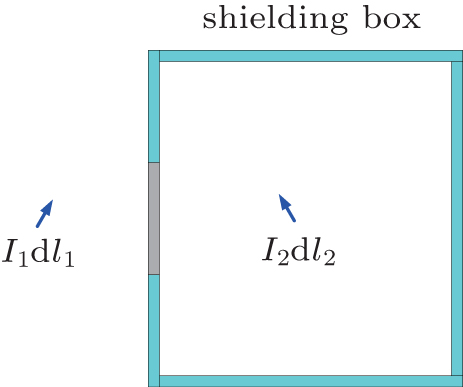 | Fig. 1. Two electric dipoles placed inside and outside a shielding box, respectively. |
According to the reciprocity principle, we obtain

Here E12 refers to the penetration field, which is defined as the component (parallel to I1d l1) of the E-field observed at the position of I1d l1 but produced by I2d l2. E21 can be understood in a dual way. Assuming that the two dipoles have identical moment, E21 then equals E12. Since the reciprocity principle is always valid, whether the shielding box exists or not, both the E0 and Es can be calculated by this principle. Moreover, by adjusting the external dipole’ s position, direction, and its distance from the shielding box, the influences of the propagation direction, polarization direction, and also the near/far field SE can be contained in this model. On the other hand, by adjusting the internal dipole’ s position and direction, the penetration field at any position inside the cavity can also be obtained.
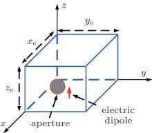
Figure 2 shows an empty rectangular cavity excited by an electric dipole placed inside it. The x, y, and z dimensions of the cavity are xe, ye, and ze, respectively. The z-directed dipole is located at the point (xs, ys, zs). An aperture is cut around the center of the x = xe wall. The aperture is covered by a conductive sheet layer with a thickness of t and a conductivity of σ . It is assumed that the cavity wall is perfectly conductive.
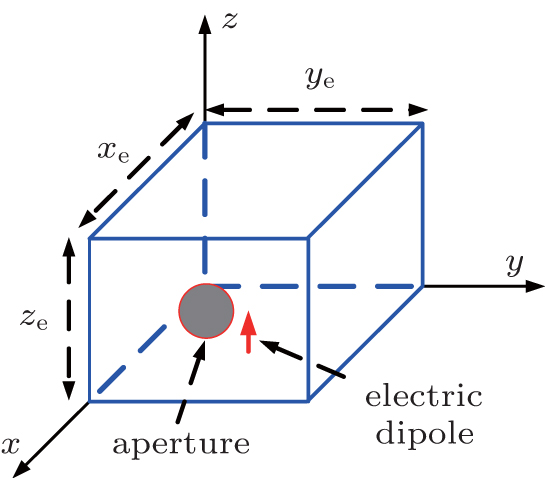 | Fig. 2. A rectangular cavity with a circular aperture covered by a conductive sheet layer is excited by an electric dipole placed inside the cavity. |
The problem of solving the leakage field is divided into three separate sub-problems: (i) the interior problem of determining the “ unperturbed” field distribution inside the cavity with the aperture short-circuited; (ii) the transmission problem of determining the tangential E-field on the outer wall of the conductive layer; (iii) the exterior problem of calculating the leakage field based on the equivalent surface magnetic current on the outer surface of the conductive layer.
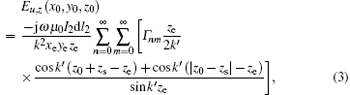
The solution of the interior problem can be expressed using Green’ s function of a rectangular cavity.[15, 16] These expressions are listed here again for convenience. The unperturbed E-field
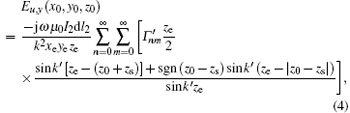

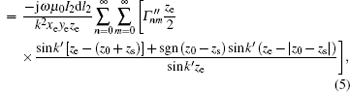
where ω is the angular frequency, μ 0 is the vacuum permeability, k = ω /c is the wave-number with c denoting the speed of light, sgn(x) is the sign function, and

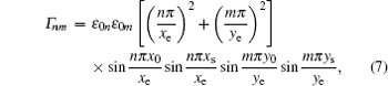
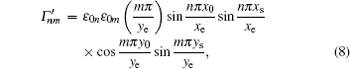
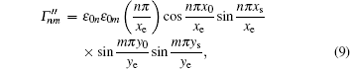
where ɛ 0n (ɛ 0m) = 1 for n = 0, and ɛ 0n (ɛ 0m) = 2 for n ≠ 0.
Once the E-field is known, the unperturbed H-field can be obtained by using the Faraday’ s electromagnetic induction law,


By the coordinate alternation method, the above model is also feasible for x-directed or y-directed electric dipole. Then, by using the superposition principle, the model can be expanded further to account for any direction-directed electric dipole source. With the increase of n and m, k′ will become an imaginary number, the sine terms in these denominators will cause an exponential attenuation, and the series begins to converge rapidly. However, for the field point having the same z-coordinator as the dipole’ s, the convergence becomes slow due to the fact that the denominator and the numerator have identical exponential growth rates. In this case, the values of n and m must be increased further to achieve stable results.
The transmission problem is solved by introducing the transfer impedance Zt, which is defined as Eto = Hti × en, where Eto is the tangential E-field on the outer surface of the sheet, Hti is the tangential H-field on the inner surface of the sheet, and en is the unit normal vector of the outer surface. Here, Hti is approximated by using the unperturbed H-field. For a good conductor, the transfer impedance Zt can be approximated by the corresponding impedance of a sheet with infinite extension against a plane wave of normal incidence

where Z0 = (μ 0/ɛ 0)1/2, Zc = [jω μ 0/(σ + jω ɛ 0)]1/2, and kc = [ω μ 0 × (ω ɛ 0– jσ )]1/2.
Then, the leakage field can be considered as the field produced by an equivalent surface magnetic current distribution on the outer surface of the sheet layer. One approximate solution to this complex 3D electromagnetic scattering problem is to expand the apertured wall infinitely. This new geometry is easy to treat by introducing corresponding image surface magnetic current. Then, the leakage field can be expressed as the field generated by the surface magnetic current distribution in free space circumstance with its surface density Km = 2Eto× en. The last procedure essentially involves the calculation of a surface integral, which is carried out numerically. Therefore, this model should be regarded as a semianalytical approach.
In the process of developing the present model, three approximations are made. a) On the inner surface, the tangential H-field is approximated by the unperturbed field; b) the electromagnetic penetration through the sheet is described by the transfer impedance; c) the finite size wall is replaced by an infinite surface. As a result, the validation of this model requires that i) the sheet has good electrical conductivity; ii) the aperture should not be very close to the edge of the wall and its size should be smaller than the size of the wall; iii) the observation point of field intensity should be located within the space around the right ahead of the aperture.
We assume that xe = ye = 30 cm, ze = 12 cm, t = 1 mm and that the sheet layer is made of non-magnetic material with the same permeability and permittivity as the free space’ s. Only the z-component E-field is used in the SE calculation, since it is usually the primary one among the three components of the E-field for the present configuration.
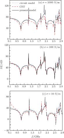
First, we consider a 5 cm× 5 cm square aperture. For such a shape, the circuital model in Ref. [5] can also be applied. Figure 3 shows the dependences of the SE on the frequency for three different values of σ . For the “ circuital model” curves, the exciting source is a plane wave propagating along the − x axis and polarized in the z axis direction, and the position where the SE is observed is at P (14.75 cm, 15.25 cm, 11.75 cm). For the curves “ present model” and “ CST” , the exciting source is an electric dipole placed at the same position as P, and the SE observation point is in front of the aperture 1 m away from the aperture. “ CST” represents the results from the frequency-domain solver of the CST MWS.[17] It can be observed that the curves within a broad frequency range are in good agreement. However, when the frequency is below 0.1 GHz, curves of both the present model and the circuital model deviate from those of “ CST” . This deviation is more evident at lower conductivity as displayed in Fig. 3(c). The excellent agreement between the present model and the circuital model indicates that the present model is feasible for the prediction of the SE against an external plane wave. Of course, to this end, the observation point should be selected to be within the far field region of the aperture. With the increase of the conductivity, the difference between the present model and the circuital model decreases. With the increase of the conductivity, the relative error basically keeps unchanged, although the absolute error between the present model and the CST model increases. In terms of the computer running time, the present model and the circuital model have little difference from each other by about one minute for 50 frequency points. However, the frequency-domain solver of CST MWS spends about 60 times the time needed by the present model.
 | Fig. 3. Shielding effectivenesses of a 5 cm× 5 cm aperture from the circuital model, the present model, and the CST model for three different conductivities. |
Some crests, where the SE increases sharply, can be found in Fig. 3. Also, some troughs, where the SE decreases sharply, can be observed. As is well known, the troughs result from the cavity resonance effect, which happens if the wave frequency equals the resonance frequency of an electromagnetic mode of the cavity with the resonance frequency expressed as
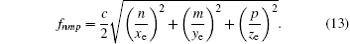
According to Eq. (13), several troughs are identified such as the TM110 resonance at 0.71 GHz, the TM210 resonance at 1.12 GHz, the TM310 / TM130 resonance at 1.58 GHz, and the TM230 resonance at 1.8 GHz. Wherein, the sign “ TM” (transverse magnetic) means that the z component of the H-field is zero. On the other hand, the potential reason for the crests may include that the aperture is at the position where the unperturbed tangential H-field (here, it is Hy) is zero, which makes the equivalent surface magnetic current reduce greatly; the z component of the E-field observed at the position where the electric dipole is placed is zero, which makes the coupling between the dipole and the electromagnetic modes very weak. Both the reasons can be attributed to the standing-wave field structure of the cavity electromagnetic modes. At 1.12 GHz, the TM120 mode is also in resonance. For this mode, Hy = 0 happens in the center of the aperture, which is responsible for the crest around 1.12 GHz. Similarly, the TM320 mode is responsible for the crest around 1.8 GHz.
Figure 4 shows the SE in the case of a circular aperture with radius R, where σ = 100 S/m, the field point– aperture distance d = 1 m, and the dipole is located at (15 cm, 15 cm, 2 cm). The present model is consistent with the CST solution. A comparison between Fig. 4(a) and Fig. 4(b) exhibits about 20-dB reduction of the SE with radius increasing from 1 cm to 3 cm.
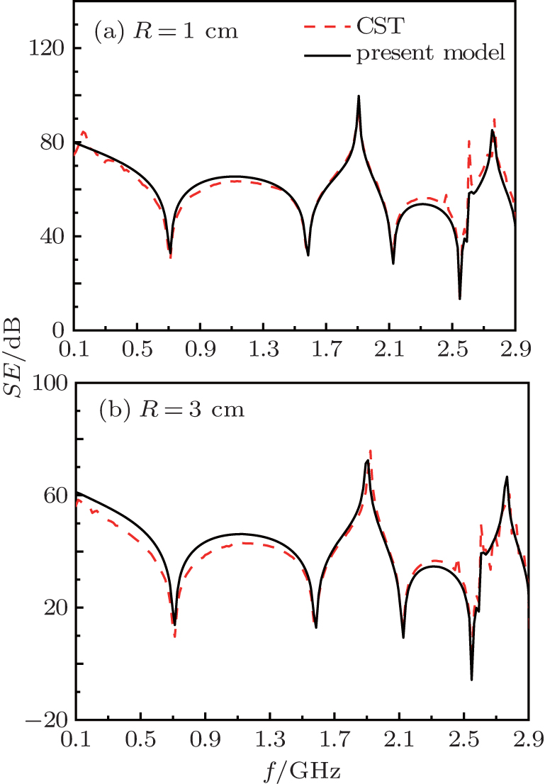 | Fig. 4. Shielding effectivenesses of a circular aperture with a radius of R versus frequency for σ = 100 S/m and d = 1 m. |
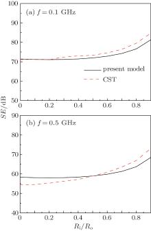
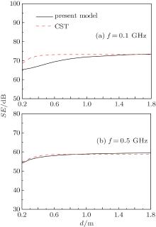
Annular aperture is considered in Fig. 5, where σ = 100 S/m, d = 1 m, the outer radius of the annular aperture is R0 = 2 cm, and its inner radius Ri increases gradually from zero to 0.9R0. Although the agreement between the two models is not very satisfactory, the tendency that SE increases with aperture area decreasing is supported by the two methods. In this process, about 8-dB increment is observed from the present model and about 15 dB from the CST model. When Ri is fixed to be 1 cm, the variations of the SE versus distance d are displayed in Fig. 6. It can be seen that the SE increases gradually with d increasing and tends to a stable level when d reaches some value. Such a value is not easy to determine accurately, since it may be affected by the frequency, shape, and dimensions. By and large, this value is about one free space wavelength. With the decrease of d, the increase of the penetration field Es is at a speed faster than that of the reference field E0, since the aperture is closer to the field point than the dipole. This may be the reason why the SE is reduced with the decrease of d within the near-field region.
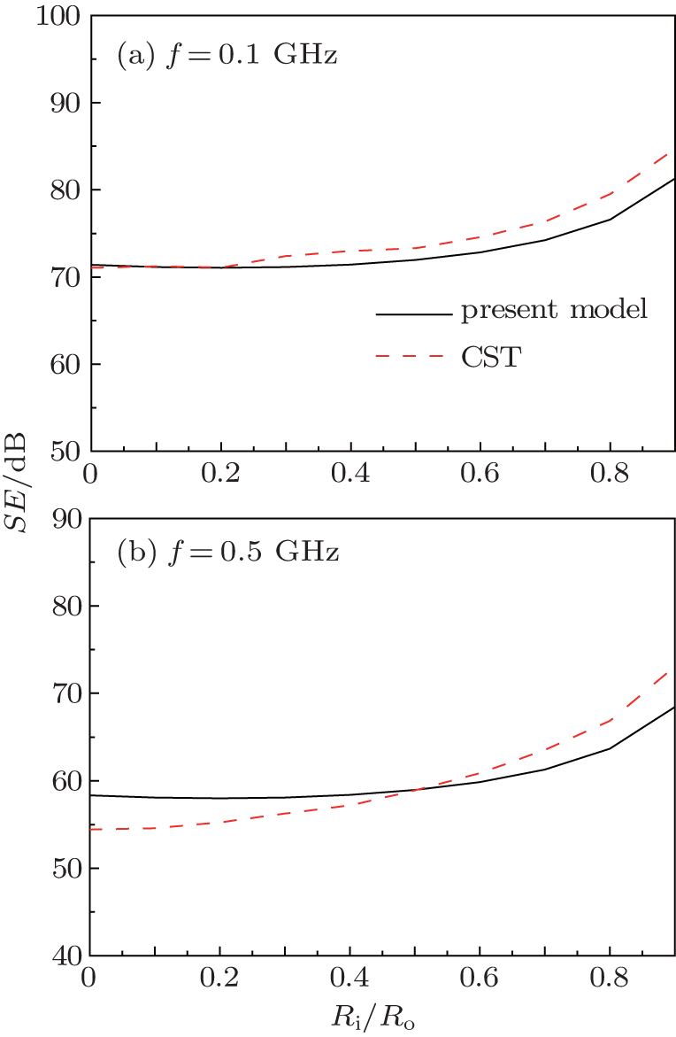 | Fig. 5. Dependences of the shielding effectiveness of an annular aperture with fixing outer radius R0 = 2 cm on its inner radius Ri for σ = 100 S/m and d = 1 m. |
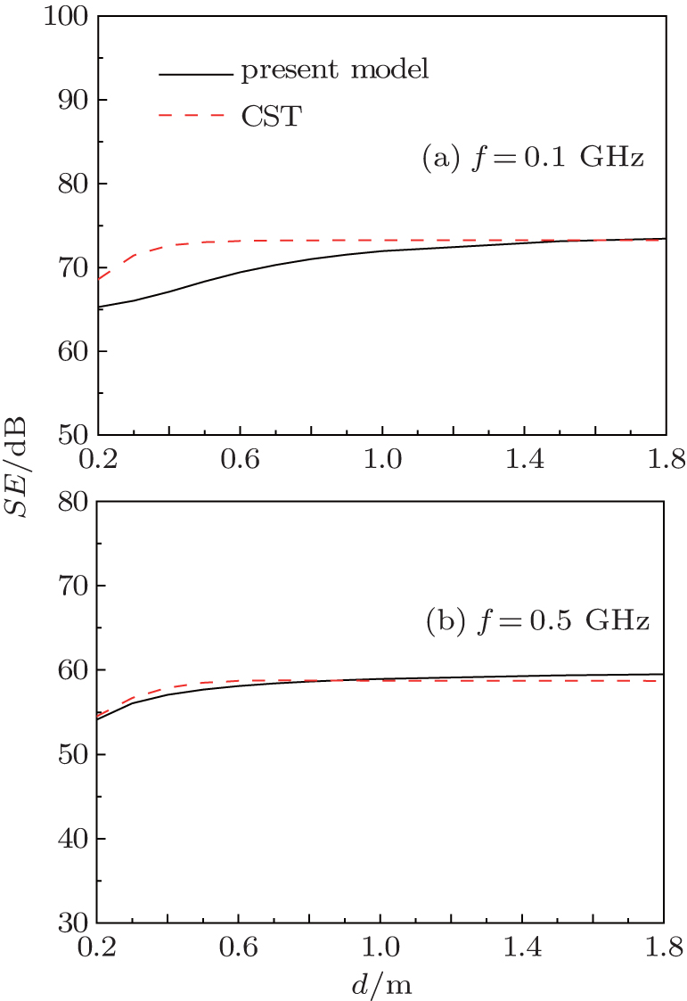 | Fig. 6. Variations of the shielding effectiveness of an annular aperture with distance d for 1-cm inner radius, 2-cm outer radius and σ = 100 S/m. |
A semi-analytical model is formulated to calculate the field penetrating from a rectangular box with a rectangular aperture covered by a conductive sheet and excited by an electric dipole placed inside the box. This model is the combination of the Green’ s function of the closed cavity, the transfer impedance description of the conductive sheet layer, and the replacement of surface electric field by using an equivalent surface magnetic current distribution. Based on the reciprocity principle, the model can be used to predict the shielding effectiveness of the box against an electric dipole source placed outside the box. By adjusting the position and direction of the dipole, both near-field and far-field cases can be contained in this model. In addition, the shape of the aperture is not restricted. This model can also be extended easily to treat multiple apertures. Applications of this model to the rectangular, circular, and annular apertures are implemented, respectively. Good agreement is achieved among the present model, the circuital model, and the CST model.
| 1 |
|
| 2 |
|
| 3 |
|
| 4 |
|
| 5 |
|
| 6 |
|
| 7 |
|
| 8 |
|
| 9 |
|
| 10 |
|
| 11 |
|
| 12 |
|
| 13 |
|
| 14 |
|
| 15 |
|
| 16 |
|
| 17 |
|