


Transformation optics for efficient calculation of transmembrane voltage induced on cells
[Liao Yin-Honga) , Zhu Hua-Chenga) , Tang Zheng-Minga), b) , Huang Ka-Ma†a)  ]
]
]
 |


†Corresponding author. E-mail: kmhuang@scu.edu.cn
*Project supported by the National Key Basic Research Program of China (Grant Nos. 2013CB328900 and 2013CB328905).
We present a novel efficient approach in calculating induced transmembrane voltage (ITV) on cells based on transformation optics. As cell membrane is much thinner than the dimension of a typical cell, discretizing the membrane needs numerous meshes. Using an anisotropic medium based on transformation optics, the thickness of the membrane can be exaggerated by at least one order, which eliminates rigorous mesh refinement and reduces unknowns greatly. The accuracy and efficiency of the proposed method are verified by a cylindrical cell model. Moreover, the influence on ITV with bound water (BW) layers is also studied. The results show that when cells are exposed to nanosecond electric field, BW layers should be rigorously considered in calculating ITV.
The interaction between electric field and cells has received much attention for decades. When cells are exposed to an electric field, the penetrability of the cell membrane may increase, which leads to the formation of transient hydrophilic pores in the membrane.[1– 3] This phenomenon is called electroporation, which has been widely used in many applications, such as fusion of cells, introduction of drugs into cells, and the treatment of cancer.[4– 6] However, the physical mechanism of electroporation is admittedly poorly understood and research reveals that it is related to induced transmembrane voltage (ITV) across the cell membrane.[7– 9] Hence, accurate ITV is critical in clarifying the mechanism of electroporation.
In the past, many methods have been proposed to calculate ITV, including finite difference method (FDM), finite element method (FEM), and finite volume method (FVM).[10– 12] Nevertheless, these methods all need to discretize computational domains. As the cell membrane is much thinner than the dimension of a typical cell, describing the cell membrane with good accuracy makes mesh cumbersome.[13] In order to reduce meshes, the jumped boundary method and the scaling method are usually employed. With the jumped boundary method, the cell membrane is equivalent to a boundary with zero thickness.[14] With the scaling method, the membrane is replaced by a thicker one with higher permittivity and conductivity within the membrane.[15]
Nevertheless, the two equivalent methods both bear their inherent limitations. It has been reported that the error of the jumped boundary method increases with the thickness of membrane. When cell membrane is only 1% of the cell dimensions, the error reaches nearly 10%.[16] With the scaling method, the error also remains a high value.[17] For example, when a spherical cell is exposed to nanosecond electric pulses, the error reaches 10%.[18] Furthermore, recent research shows that ITV values even with variation less than 3% result in pore density variation being 80%.[19] Besides, as is well known, the cell membrane consists of some complicated structures, such as hydrophilic headgroup regions and bound water (BW) layers. These structures may affect electric distribution within cells.[19, 20] Hence, there remains a need for an efficient approach that can both calculate ITV accurately and deal with the problems involved in cells with complex structures.
On the other hand, transformation optics has attracted much attention in recent years. For example, Pendry et al.[21] and Schurig et al.[22] used transformation optics to design an invisible cloak, which was one of the most important progressions in electromagnetics and optics in recent years. Besides, some novel devices have also been reported based on transformation optics, such as concentrators, multi-window invisible cloaks, and beam squeezers.[23– 25] In addition, transformation optics is also extended to other fields, including acoustics and thermodynamics.[26– 28] Indeed, transformation optics can date back to the 1990s. In 1996, Ward and Pendry et al. used this theory to reduce the unknowns in computing Maxwell’ s equations in complex geometries encountered in photonic band structure.[29] In this work, they employed an adaptive co-ordinate system to expand the length scale by renormalizing permittivity and permeability, which is extremely convenient to tackle multi-scale problems in computers. Moreover, Milton et al. proved that the Laplace equation also stays form-invariant in different coordinate systems.[30] Hence, this provides us with a potential way of calculating ITV on cells.
In the present paper, we propose an efficient approach to calculating ITV on cells using transformation optics. Based on the form-invariance of the Laplace equation, the thickness of the cell membrane can be exaggerated by using an anisotropic medium, which can reduce meshes greatly. Importantly, using the proposed method, we can handle the problems with sophisticated structures in cells. A cylindrical cell model shows that the proposed method can enhance computational efficiency greatly with high accuracy. Besides, utilizing the proposed method, we calculate ITV involved with BW layers. The results show that the BW layers should be rigorously considered when cells are exposed to a nanosecond electric field.
Generally, transmembrane voltage in cells is determined by the Laplace equation.[12] As mentioned above, it is difficult to generate meshes to discretize cell geometry due to the large ratio of cell dimensions to membrane thickness.[14] As Milton et al. proved that the Laplace equation also remains form-invariant in different coordinate systems, which is similar to Maxwell’ s equations, [30] this inspires us that ITV may be obtained by exaggerating the thickness of membrane in other coordinates through using transformation optics. Thus, dense meshes can be eliminated.
In a time-harmonic field, the Laplace equation can be expressed as

Here, ɛ (r) is complex permittivity and r is the position vector. We define a coordinate transformation as

where r′ is the position vector in the new coordinate. Correspondingly, the voltage in the new coordinate satisfies[30]

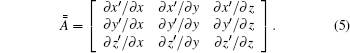
with

Here, 
For an isotropic medium, equation (4) can be simplified into

with

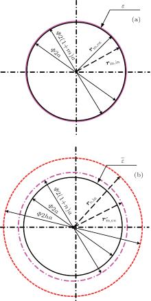
Usually, a cell model consists of cytoplasm Ω c, membrane Ω m, and extra-cell medium Ω e as shown in Fig. 1(a). Interior membrane boundary and exterior membrane boundary are denoted by ∂ Ω m, in and ∂ Ω m, ex, respectively. In order to perform transformation, we add a virtual boundary ∂ Ω e, in within the extra-cell medium in Fig. 1(b). In the new coordinate, the cell membrane is amplified by stretching boundary ∂ Ω m, ex into 


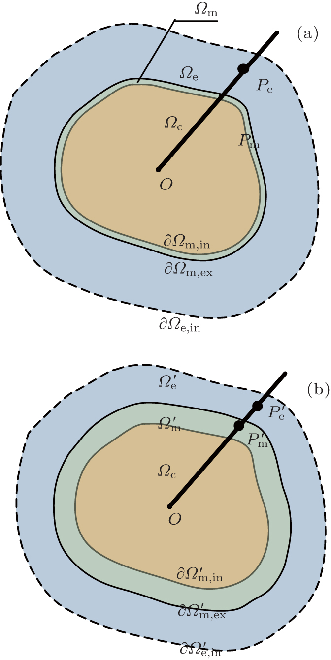 | Fig. 1. Coordinate transformation for cell membrane. |
In the membrane, point Pm (r) in the original coordinate is mapped to 

Here, rm, in, rm, ex, and 

where re, in denotes the position vectors of points at ∂ Ω e, in.
 | Fig. 2. Sketch of a cylindrical cell. |
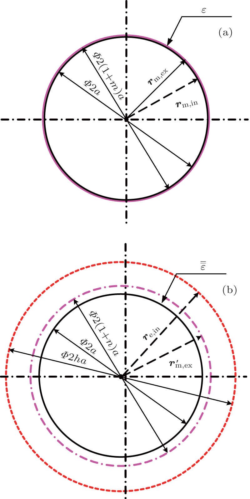
Also, we take an example of a cylindrical cell model to demonstrate the proposed method as shown in Fig. 2. The radius of the cytoplasm and the thickness of the membrane are a and ma, respectively. In the new coordinate, the thickness of the membrane is na and the radius of boundary ∂ Ω e, in is ha. In the membrane, position vectors corresponding to boundaries ∂ Ω m, in, ∂ Ω m, ex, and


where ax and ay are unit vectors of the coordinate system. According to Eqs. (8), (10), (11), and (12), we derive relationships between the original coordinate and the new coordinate as follows:


where


and

Based on Eq. (5), the tensor in Eq. (7) can be expressed as
with


and

where 
According to Eqs. (9), (11), (12), (13), (14), and (17), we find that the tensor of complex permittivity in compressing domain is similar to Eq. (18) with the parameters of

and

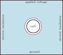
A cylindrical cell model is used to verify the efficiency and accuracy of the proposed method as shown in Fig. 3. The cylindrical cell is surrounded by a square with a size of 10 μ m × 10 μ m. The radius of the cylindrical cell is 1 μ m and the thickness of the membrane is 10 nm. In the new coordinate, the thickness of the membrane is 100 nm and the radius of the boundary ∂ Ω e, in is 1.2 μ m.
 | Fig. 3. Computation domain for the cylindrical cell. |
| Table 1. Dielectric parameters of cell compartments. |
Dielectric characteristic of each cell compartment can be described as[19]

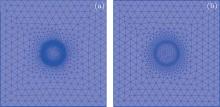
where ɛ s and ɛ ∞ represent the permittivity values under static conditions and extremely high frequencies, respectively, and frelax is the relaxation frequency. The dielectric parameters are displayed in Table 1.[19] Boundary conditions are shown in Fig. 3, in which the applied voltage is 1 V. The model is performed by FEM software with triangle elements. The mesh size is 0.5 μ m and it decreases toward the membrane as shown in Fig. 4.
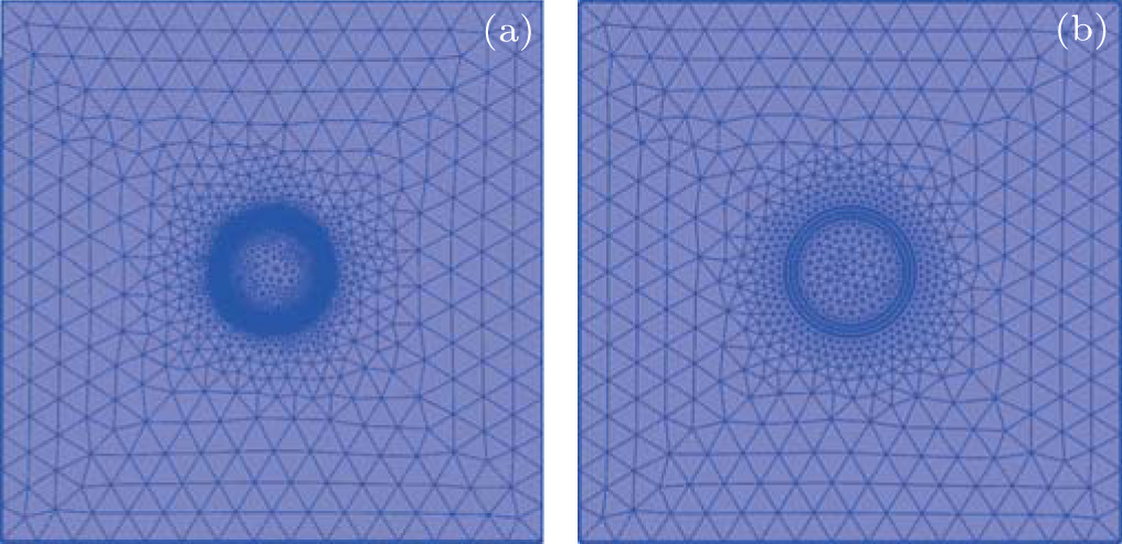 | Fig. 4. Meshes of the model: (a) by original FEM and (b) the proposed method. |
Table 2 shows the number of mesh elements when using the proposed method is much lower than when using original FEM. The numbers of unknowns when using original FEM and the proposed method are 3361 and 27629, respectively. Clearly, it seems that the proposed method can reduce the numbers of meshes and unknowns greatly. In this model, the cell dimension is 100 times the thickness of membrane. Specifically, by using the original FEM it is shown that the number of unknowns increases dramatically with increasing the ratio of cell dimension to membrane thickness. For example, when the radius of cytoplasm becomes 10 μ m, it is hard to generate meshes in personal computers by the original FEM. Besides, it has been reported that there are BW layers on each side of the membrane, whose thickness ranges from 0.5 nm to 2 nm.[31] The cell dimension is several thousand folds of the thickness of BW layer. The original FEM cannot deal with these problems, but they can be solved readily by the proposed method.
| Table 2. Comparison of results between original FEM and the proposed method. |
Figure 5 shows ITV across the membrane with a working frequency of 1 MHz. The black line (with solid squares), red line (with solid circles), and blue line (with solid rhombi) represent the results by the original FEM, the proposed method and the previous scaling method in Ref. [17], respectively. The maximum ITV by the previous scaling method is 0.1991 V, which is 7.8% larger than that by the original FEM. It has been found that pore density varies sensitively with ITV value. For example, ITV values with variation less than 3% result in pore density variation being nearly 80%.[19] The previous scaling method will lead to inaccurate results in studying electroporation. On the other hand, the results obtained by the proposed method are in good agreement with those obtained by the original FEM. The maximum ITV obtained by using the proposed method is 0.1847 V, which is identical to that by using the original FEM. It indicates the proposed method can provide us with an efficient and accurate technique to calculate ITV.
 | Fig. 5. Variations of transmembrane voltage across the membrane with frequency of 1 MHz, obtained by different methods. |
Based on the proposed model above, we study the influence of BW layers on ITV with thickness values of 0.5 nm and 2 nm, respectively. Figures 6(a) and 6(b) show the variations of ITV across the membrane with arc length at working frequencies of 1 MHz and 1 GHz, respectively. In Fig. 6(a), the influence of BW layers on ITV can be ignored at 1 MHz. While the working frequency is 1 GHz, we can see significant changes of ITV with BW layer. In Fig. 6(b), when the thickness of the BW layer is 0.5 nm, the maximum value of ITV along the arc is 0.0153 V, which is 5.45% larger than that without BW layers. As the thickness of the BW layer increases to 2 nm, the maximum ITV value decreases to 0.0147 V and this is only 1.38% larger than that without BW layers. The pore density is sensitive to the ITV value, which suggests that when cells are exposed to a nanosecond electric field, BW layers should be rigorously considered in simulation.
 | Fig. 6. Transmembrane voltage across the membrane with BW layers with frequencies at (a) 1 MHz and (b) 1 GHz. |
In this paper, we propose an efficient approach to calculating ITV across a cell, based on transformation optics. The Laplace equation is mapped to a general form in which the permittivity is anisotropic. By mapping the original space to the transformed space, the need for rigorous local mesh refinement to discrete thin membrane is eliminated, thus reducing unknowns and improving computational efficiency. Specifically, we derive the expressions of anisotropic permittivity for a cylindrical cell. A simple example is presented to verify the proposed method. Compared with previous methods, the proposed method shows good accuracy, which provides a powerful technique to investigate the physical mechanism of electroporation with sophisticated structures. Using the proposed method, the influence of BW layers on ITV is also studied. The results show that the BW layers can affect ITV significantly at 1 GHz. Hence, for the case where cells are exposed to a nanosecond electric field, the BW layers should be rigorously considered in the simulation.
| 1 |
|
| 2 |
|
| 3 |
|
| 4 |
|
| 5 |
|
| 6 |
|
| 7 |
|
| 8 |
|
| 9 |
|
| 10 |
|
| 11 |
|
| 12 |
|
| 13 |
|
| 14 |
|
| 15 |
|
| 16 |
|
| 17 |
|
| 18 |
|
| 19 |
|
| 20 |
|
| 21 |
|
| 22 |
|
| 23 |
|
| 24 |
|
| 25 |
|
| 26 |
|
| 27 |
|
| 28 |
|
| 29 |
|
| 30 |
|
| 31 |
|